

Drawings and documents
USPTO scan
The patent as scanned by the USPTO
-
 Page 1
-
 Page 2
-
 Page 3
-
 Page 4


U.S. Patent and Trademark Office · Google Patents
Show the transcription Hide (1,040 words)
Machine transcription (LightOnOCR) of the pages as scanned by the USPTO, most of them the handwritten copies made when the records were restored after the 1836 fire. Not checked; it can misread handwriting, so compare it with the scan.
Page 2.
United States Patent
Patent No.: X8778
John W. Cope, Franklin, Tenn.
Letters Patent
The schedule referred to in these Letters Patent and making part of the same containing a description in the words of John W. Cope himself of his improvement in the Straw cutting machine.
To all to whom these presents shall come: We it known that I John W. Cope of the county of Franklin and State of Tennessee, have invented a new and useful improvement in the straw-cutting machine, and that the following is a full and exact description of the construction and operation of his said machine as invented by me. The frame is constructed of timbers eleven feet three inches in length, four by six inches in width and thickness, and supported by four legs of timber of the same size. This frame is three feet high and twenty-two inches wide from inside to outside and fourteen inches in the clear. This frame is confined together by a piece of timber of the same size let on tenons cut on the side pieces of the frame by mortices in each end of this end piece and at the other end by a piece of timber four inches square and extending through each side piece by tenons. At one end of this frame is fixed upon each rail cap pieces two feet four inches long, four by six inches, these caps are confined to each rail of the frame by two iron or wooden bolts. These caps and the side pieces of the frame are rabbeted for three feet three inches one inch on each of the side rails and an inch in each of the caps. This forms a groove for a frame upon which the knife is placed, this groove extends to the end of the frame. On this groove is placed a frame two feet four inches in length and sixteen inches in width, constructed of timber two inches square. The knife which is placed upon this frame is two and a quarter inches wide, half an inch thick at the centre. The upper side is to be perfectly true bearing from the centre on the under side each way to an edge. This knife is placed across the centre of the frame diagonally at an angle of forty-five degrees and is fastened at each to the frame by iron bolts or wood screws. The knife may be made as above described with a back in the centre.
Page 3.
United States Patent
Patent No.: X8778
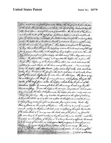
from end to end one fourth of an inch thick, this knife is to be from the face to the back, three fourths of an inch thick. The object of this back is to keep the step board clean and is to be made of good steel. On the centre of this frame and being the centre of the cusp pieces, is placed a hopper made of inch plank four by twelve inches in width for twelve inches and for the remaining twelve inches the hopper being two feet in length is reduced to six or eight inches at top the mean cage being left open. This hopper is confined to the cusp pieces by keys that extend through the cusp pieces and a slit into each side of the hopper by grooves the notches in the cusp pieces being half an inch wide than the keys which are confined by their wedges at each end of these keys above and below. The object of these wedges is to regulate the hopper too or from the knife. This hopper is to be faced with a steel one inch wide and the eighth of an inch thick at the lower end of the inside. Immediately under the hopper is the step board three and a half inches wide and twelve inches long beveled on the face from the centre each way so as to make it one eighth of an inch thicker on the sides than the other edges. This board is raised or taken from the knife by means of a screw which passes through the centre of the cusp pieces under the hopper which holds the frame of the machine together by means of which the straw may be cut any length deemed necessary. Under the hopper this part of the frame is attached to a board extending from near the wheel to the floor under the hopper fourteen inches wide and about two feet long. This may be called the apron and the object of which is to throw the straw as it is cut into a place at the opposite end of the frame. A wheel of heavy wood four feet in diameter four or five inches thick. This wheel is placed on the inside of the frame. This wheel is turned by means of a crank resting in the frame at each end and passing through the centre of the wheel, which is to run as near the back side of the frame as possible. The crank is to be eight inches in length and three in width and then to extend on the outside of the frame to where a handle is affixed; the crank is to be made of iron bar one inch square and the grooves to be confined on the frame by small strips of wood fastened with wood screws. The wheel being in the frame the crank is thrown in the centre to which is affixed a pinion of the kind of the patent which is attached
Page 4.
United States Patent
Patent No.: X8778
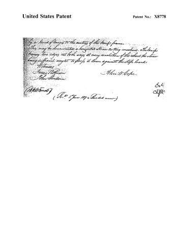
By a kind of plunger to the centre of the knife frame.
This may be denominated a horizontal straw cutting machine. The knife
having two edges cut both ways at every revolution of the wheel the straw
having sufficient weight to force it down against the stop board.
Witnesses
James Robinson
John Gordon
John W. Coape
(10450 words)
(Rec’d 1st June 1837 & Entered same)
Exd
Clyw.
Published accounts: journal notice
Notice in the monthly list of patents
Journal of the Franklin Institute, new ser., vol. 15 (1835), p. 435 · View the page
249. Straw cutter.-John W. Cope, Franklin, Tenn.
Published accounts: journal notice
Notice in the monthly list of patents, with remarks
Journal of the Franklin Institute, new ser., vol. 16 (1835), p. 332 · View the page
79. For a Straw Cutter; John W. Cope, Franklin county, Tennessee, April 24.
Remarks. The straw to be cut is put endways into a hopper, in which it is to descend by its own gravity. A sliding frame carrying an oblique knife, with two cutting edges, traverses backwards and forwards under the hopper, being moved by a pitman from a crank shaft, regulated by a fly wheel. There is no claim made, but this had been already done in at least one of the ten straw cutters patented in 1833, several of which resemble that now under consideration; we do not think it necessary to turn to the particular one which is its counterpart.
About this record
- Patentee
- DATAMP
- Date
- the Name and Date index of patents, DATAMP, USPTO records
- Invention
- DATAMP
- Listed in
- the Name and Date index of patents, DATAMP, USPTO records, Jim Shaw's X-patent list, the Journal of the Franklin Institute, Burke's List of Patents (1847)
- The Franklin Institute's journal gives a different date.
- Burke's 1847 Patent Office list gives the same patent.