

Drawings and documents
USPTO scan
The patent as scanned by the USPTO
-
 Page 1
-
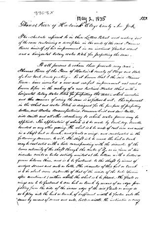 Page 2
-
 Page 3
-
 Page 4
-
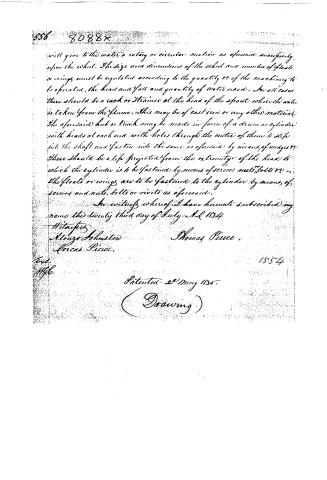 Page 5


U.S. Patent and Trademark Office · Google Patents
Show the transcription Hide (1,547 words)
Machine transcription (LightOnOCR) of the pages as scanned by the USPTO, most of them the handwritten copies made when the records were restored after the 1836 fire. Not checked; it can misread handwriting, so compare it with the scan.
Page 1.
8808X
T. Pierce
Water Wheel,
Patented May 2, 1835.
Fig. 1.

Fig. 3.

Fig. 5.

Fig. 2.

Fig. 4.

Page 2.
9808X
May 2, 1835
Thomas Pierce of Hartwick & Otsego County - New York.
The schedule referred to in their Letters Patent and making part of the same containing a description in the words of the said Thomas Pierce himself of his improvement in an inclined floated wheel and a horizontal Rotary water Pitch for propelling the same.
To all persons to whom these presents may come.
Thomas Pierce of the Town of Hartwick county of Otsego and State of New York sends greeting - Be it known that I the said Thomas Pierce - have invented a new and useful improvement not used or known before in the making of a new inclined floated wheel with a horizontal Rotary water Pitch for propelling the same - which invention and the manner of using the same is as follows to wit. This improvement in the wheel and water Pitch is designed for the purpose of propelling cotton, and Woolen Manufactories, Common Sift and Saw Mills, side Mills and all other machinery to which water power may be applied. The application of which is to be made by level, eq. tumble, tanded or any other gearing. The wheel is to be made of cast iron and consists in a shaft hub or trunk, and floats or wings, and constructed in the following manner, to wit. The shaft is to be round the hub or trunk may be cast solid with a hole corresponding with the diameter of the lower extremity of the shaft through the centre of it, or in form of two circular circles or tubes solidly united at the bottom with a hollow or groove between them, and is to be fastened to the shaft by means of wedges screws and nuts or bolts. The diameter of this hub or trunk is to be about seven sixteenths of that of the inside of the tube (herein after mentioned) within which the wheel is to be placed. The floats or wings are to be fastened to one hub or trunk by means of an edge projecting from the side of the inner edge of the said floats or wings so as to play into the hub or trunk, of sufficient width to fasten onto the same by means of screws and nuts, bolts or rivets. The inclination or course of.
Page 3.
of the floats or wings is to be so as to lean towards and over the water pitch, so that the water in its rotary or circular motion in the tube will have a full effect upon them. After operation the wheel is to be placed upright in a circular tube and supported at the extremities in the usual manner of upright wheels by bearings or pivots. The tube is to be of sufficient size in length and diameter to correspond with that of the wheel. It is to be made tight at the bottom and may extend from the surface of the water in the creek below the dam or at low tide to any depth necessary for the purpose of increasing the head or the power of the water upon the wheel. After the purpose of setting the tube, wheel, duct, and spout below the surface of the water or ground as the case may be, or the location requires, it will be necessary to sink a cistern or box in the water or ground as aforesaid of sufficient size in height and diameter to contain the tube, duct, and spout. The water is conducted down to the bottom of the tube in which the wheel is placed in a spout from the flume, and taken from the side of the spout at the bottom and carried in a duct lying horizontally and conducting until it begins to enter the main cavity of the tube. The duct continues horizontally around the tube in a rotary or circular direction partly without and partly within the main cavity of the tube through which the water passes in such a manner as to have an equal and continued bearing on all the floats or wings in the wheel, and this rotary or circular current and uniform bearing upon all the floats or wings in the wheel is continued until the principal force of the water is exhausted in operating upon the wheel. After which it passes in the rotary or circular manner as aforesaid, off at the top of the tube. The spout duct and tube are also to be made of cast iron. The whole or any part of the said wheel, tube duct or spout may be made of wood or any other material. The following supposition will serve more fully to exemplify the construction and operation of this improvement to operate one run of mill stones. Suppose twelve feet head of water. The shaft of the wheel should be about fourteen feet in length and about two and a half inches in diameter, the hub or tank should be about twelve inches in length and seven inches in diameter.
Page 4.
The floats or wings should be about twelve inches in length and four and a half inches in width making the wheel when put together about eighteen inches in diameter. The wheel is to be placed in the tube as aforesaid, the bottom of the tube, the duct and spout should be settled in the water or ground as aforesaid about twelve feet. The duct when it enters the cavity of the tube, should be about four inches square through which the water passes as aforesaid on to the wheel, the spout should be about eighteen inches in diameter. The cog wheel on the water wheel shaft should be about the size of that of the trundle head on the spindle of the stone. Any part of the supposed case above mentioned may be varied at pleasure, or there may be attached to one wheel any number of runs of stones or quantity of machinery, or to one run of stones to any one set of other machinery there may be attached any number of wheels. For the purpose of gaining power from the water wheel, when the head of water is sufficient, there may be one wheel placed above another to any necessary number, joined together by coupling-budgions or gears as the case may require to operate separate machinery or all on one set or on one or more runs of stones as the case may be, the water operating in succession upon the several wheels.
For some complete and explicit illustration of the last mentioned operation, suppose thirty feet head of water. The water is taken down from the surface of the water in the glume twenty feet in a spout to the bottom of the tube in which the wheel is placed thence conducted through a horizontal duct in at the bottom of the said tube. Then in its rotary or circular operation on the wheel in the tube as aforesaid, it is elevated ten feet. Then it operates on two more wheels in the like manner in succession. The water passes out at the top of the lowest tube as aforesaid below the dam at the surface of the water or ground as the case may be. In this operation there will be three wheels, each having twenty feet of head water acting upon them in succession as aforesaid. The power of the wheel may be increased by enlarging it in all its dimensions (increasing the number of the floats or wings according) and admitting into the tube in which the wheel is placed an additional number of ducts which
Page 5.
will give to the water a rotary or circular motion as aforesaid, especially upon the wheel. The size and dimensions of the wheel and number of floats or wings must be regulated according to the quantity of the machinery to be operated, the head and fall and quantity of water used. In all cases there should be a rack or train at the head of the spout where the water is taken from the stream. This may be of cast iron or any other material. The aforesaid hub or trunk may be made in form of a drum or cylinder with heads at each end with holes through the center of them to slip into the shaft and fasten into the same as aforesaid by means of wedges. There should be a lip projected from the extremity of the head to which the cylinder is to be fastened by means of screws, nuts, bolts, etc. The floats or wings are to be fastened to the cylinder by means of screws and nuts, bolts or rivets as aforesaid.
In witness whereof I have hereunto subscribed my name this twenty third day of July A.D. 1834.
Witnessed:
Alonzo Johnston
Lorca Pice.
Thomas Pice.
1554
Patented 28 May 1835.
(Drawing)
Published accounts: journal notice
Notice in the monthly list of patents
Journal of the Franklin Institute, new ser., vol. 16 (1835), p. 70 · View the page
258. Propelling wheel. -Thomas Pierce, Hartwick, Otsego county, N. Y.
Published accounts: journal notice
Notice in the monthly list of patents, with remarks
Journal of the Franklin Institute, new ser., vol. 16 (1835), p. 387 · View the page
8. For a Water Wheel; Thomas Pierce, Hartwick, Otsego county, New York, May 2.
Remarks. This is called "an inclined water wheel, and a horizontal rotary wheel for propelling the same." The water from the head is to descend through a vertical flume, or trunk, from the lower end of which there is a horizontal duct leading to the horizontal wheel, and striking its periphery, which is furnished with oblique floats or buckets, and is contained within a curb. A second trunk or flume ascends from the former to the surface of the water in the tail race, the wheel being represented as placed at a considerable depth. The shaft of the wheel, by which machinery is to be driven, rises through this last trunk. All this we think a very bad arrangement, but if the patentee can effect what he proposes, he will more than make up for any trifling defect, as, when there is a fall of thirty feet, for example, he proposes to place three such wheels in succession, each of them to have the full pressure of twenty feet, and thus to "gain power." As his reasoning upon this subject is contrary to all reason, and occupies more space than we have to spare, we shall postpone the further consideration of the affair until some new laws of nature are enacted.
About this record
- Patentee
- DATAMP
- Date
- the Name and Date index of patents, DATAMP, USPTO records
- Invention
- DATAMP
- Listed in
- the Name and Date index of patents, DATAMP, USPTO records, Jim Shaw's X-patent list, the Journal of the Franklin Institute, Burke's List of Patents (1847)
- Burke's 1847 Patent Office list gives the same patent.