

Drawings and documents
USPTO scan
The patent as scanned by the USPTO
-
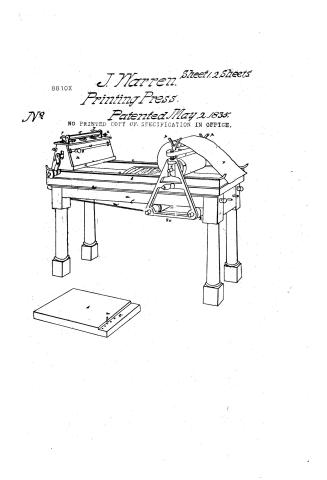 Page 1
-
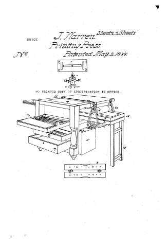 Page 2
-
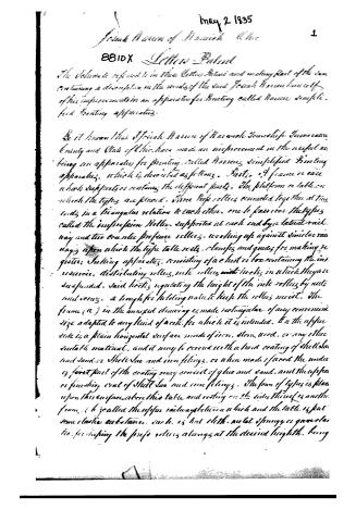 Page 3
-
 Page 4
-
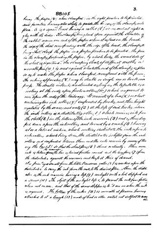 Page 5
-
 Page 6
-
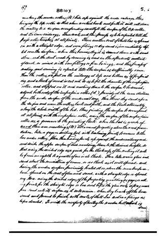 Page 7
-
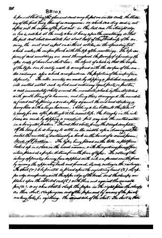 Page 8
-
 Page 9


U.S. Patent and Trademark Office · Google Patents
Show the transcription Hide (2,789 words)
Machine transcription (LightOnOCR) of the pages as scanned by the USPTO, most of them the handwritten copies made when the records were restored after the 1836 fire. Not checked; it can misread handwriting, so compare it with the scan.
Page 1.
8810X
J. Warren.
Printing Press.
Patented May 2, 1835.
NO PRINTED COPY OF SPECIFICATION IN OFFICE.
Sheet 1.2 Sheets
No
Page 2.
8810X
J. Warren. Sheets 2 Sheets.
Printing Press.
Patented May 2, 1835.
No printed copy of specification in office.
Page 3.
May 2, 1835
French Mann of Manwich. Ohio
8810X Letter Patent
The Voluntary referred to in this Patent and accompanying sheet of the same containing a description in the words of the said French Mann Mann of his improvement in an apparatus for Printing called Mann's Simplex Printing apparatus.
Be it known that French Mann of Manwich Township, Jefferson County and State of Ohio, have made an improvement in the aforesaid printing apparatus for printing called Mann's Simplex Printing apparatus, which is described as follows. Parts. A frame or case which supports or contains the different parts. The platform or table on which the types are placed. Three large rollers connected together at three ends in a triangular relation to each other, one to pass over the types called the impression Roller, supported at each end by a lateral rail way and two smaller pressure rollers, working up against similar rail ways upon which the type table rests. Clamps and guides for making register; Inkling apparatus, consisting of a chest or box containing the ink reservoir, distributing rollers, ink rollers with hooks in which they are suspended. Said hooks regulating the height of the ink rollers by nuts and screws. A trough for holding water to keep the rollers moist. The frame (a) in the uniped drawing is made rectangular, of any convenient size adapted to any kind of work for which it is intended. On the upper side is a plain horizontal surface made of iron, stone, wood, or any other suitable material, and it may be covered with a hard coating of shellac and sand, or Shellac and iron filings, or when made of wood the under or first part of the coating may consist of glue and sand, and the upper or finishing coat of Shellac and iron filings. The form of types is placed upon this surface above this table and resting on the side thereof is another frame (b) called the upper railway plate on which and the table is put some elastic substance, such as hot cloth, metal springs, or gum elastic, for keeping the press rollers always at the desired height, being
Page 4.
376. 8810X 2.
Where a brick wall allows the impression roller to a sufficient near enough to the types to give the impression, but never falling below the level of the surface. This rail may be made of wood alone, or wood with metallic rods (c) fastened on three upper sides, the impression roller having a groove at each end, in which the iron rods work, and a pin which the impression roller moves backward and forward; the impression roller (d) is made of wood or metal turned true, and of any convenient diameter from 2½ to five inches being covered with cloth, or other elastic substance, the cloth must be covered by a fine drawn seam to preserve an equal surface. The cloth being covered lastly with paper, to be changed when desired. The pressure upon the types is regulated by the screws (h) acting upon the metallic boxes (i) vice the grooves of the impression roller being counteracted by the two under rollers (k), pressing up against the under surface of the under rollers (l.) said Rail ways may be of wood, or metal or both. The under or counter pressure rollers may be made of wood with or without metallic ends, having grooves or flanges to keep them in track. The three combined rollers are kept square or at right angles with the type table by means of cords (m) or racks & pins upon the under rollers. The under rollers are placed at a suitable distance apart so that when the combination of rollers is moved the motion will be steady and the pressure uniform. To keep the paper smooth and to prevent its running before the impression roller, a bar (n) is placed over the impression roller, over which the paper is thrown. When this friction is not sufficient to prevent the paper from wrinkling, the roller (o) is thrown on to the V (p.) to add to the friction by the whole or part of its weight. This being modified by the screws of the V together with the elastic clothing of said rollers; or the paper is thrown over the roller when the least friction is desired. The regulating clamps (q) consist of two principal, hinged together and movable plates, having points fixed at convenient distances in one side and corresponding holes in the other. These are the points in the furniture which is locked up with the form and placed at any convenient distance from the types and corresponding holes in said clamps, fitting upon the points in the furniture which
Page 5.
bring the paper (S) when clamped in the right position to be printed, said furniture having also whits to guide the two ends of the clamps into place. S is a square board having a rabbet (T) on one end at right angles with its sides. The clamps being fixed upon a quadrant the elevation of the rabbet, receive one end of the paper when it is laid on the board, the edge of the sheet corresponding with the edge of the board, the clamps being shut, clamp the paper in a proper position to be printed. The form in the clamps perforating the paper, by which holes, the second side of the sheet is required. An aluminizing sheet of different densities, or more suitable (U) is used against which the end of the clamps is placed so as to make the paper when clamped, correspond with the form. The making apparatus (V) may be double or single, one or two to each press. The double roller is constructed as long as the typetable is resting at the ends upon friction rollers (W) which are provided to run upon the rods of the rails. It consists of a box (X) or chest containing two ink rollers (Y) suspended by hooks, and their height regulated by the screws and nuts (Z) at the top of said hooks, above the ink rollers is a distributing roller (1) which receives ink from the cloth (2) in the bottom of the ink reservoir (3) and is then dropped upon the ink rollers and turned by a crank (H) having also a lateral motion, which motion distributes the ink upon the ink rollers, which being done, the distributor is lifted from the ink rollers and suspended between them and the ink reservoir by means of turning the bar (5) so that the short pins (6) stand vertically. When more ink is taken from the bar is turned further round, and the long pins (7) force the distributor against the reservoir and keep it there if desired. An printing a small form the little transverse roller (8) is worked upon the distributor to carry the ink from the ends to the desired place. Above the distributor is the ink reservoir having a top (9) and lighted with a hob stopped with a screw (10). The object of the an lighted top is to prevent the ink from falling when not in use, and that of the screw stopped is to let air in when the ink is required. The bottom of the ink (11) is movable at pleasure having attached to it a trough (12) made of lead or other metal not subject to corrosion.
Page 6.
by means of a transverse motion on the same the base rolling over it keeps the rollers in contact. In the section of the base there are slots (13) through which the handles of the transverse rollers (15) pass. When being stopped with slides, reverse the base, which must not move, immovable to avoid and keep the motion within the base. The simple machine has but one ink roller the ink being taken from the reservoir by the little transverse roller which is then dropped down upon the ink roller, and worked from end to end of it, giving the handles of the transverse rollers an oblique motion by which the ink roller is turned. The object of this invention is to simplify and cheapen the printing press so as to adapt it to the condition and capacities of private citizens. It may however be used to advantage by professional printers. When used by private citizens, the type setting apparatus, type cases and all the implements necessary for printing are enclosed (if desired) in one piece of furniture such as a secretary (14), dining table, chest of drawers, or counting house desk. When combined with the secretary or similar piece of furniture the ends are closed with falling doors (15) the type table (16) and cases (17), sliding on or out at either end. The type table when drawn out is supported at the outer end by a movable standard (18). The other end remaining in or resting on the piece of furniture to which steps are affixed to step it at the proper place. But when shut up the rollers, inkings apparatus &c may be deposited in one of the drawers (19) when the types are to be handled by those who are unaccustomed to their use. I propose that the niches in the spaces, and the inserted rollers, &c should be made to correspond with those in the letters so as to admit a thread around them, confining each comprising sticks fast together, so that they can be handled while dry and clean without displacing them, and without that tact and skill which result from long experience. Mode of manufacture: The type table when made of iron or steel, may be covered with a hard coating of shell lac and iron burnings, and filings or shell lac and sand, then having the bed fastened permanently upon the under railings which are finished ready for printing, put a thick coat of shell lac dissolved in good alcohol over the surface of the bed, then three or four iron burnings and when the shell lac has set brush off the loose burnings and what sticks constitutes a kind of frame work for the coat. Put on the combination of props rollers (20)
Page 7.
8810X
5.
making the under rollers (R) take safe against the wooden railways, then bringing the top rollers so that when worked back and forth it will roll down the coating to a surface corresponding exactly to the surface of the top rollers and the lower railways, then coat and the process is to be repeated till the top rollers touch at all points. Then another coat of shell lac is spread on with a straight edge, and iron filings or dry sand is immediately sifted over the surface, when this becomes dry it is covered down with sand stone, and the dust made by scraping is used in the after coats instead of sand, or mixed with iron filings or fine borings, and this process of coating and scraping is repeated till the surface is sufficiently even. Then the rollers are put on the railways at top and bottom as if for printing and a block of wood is cut out so as to fit the diameter of the imperfect roller, and slipped on it and reaching down to the surface to be scraped, adjust both ends of the imperfect roller (d) precisely at the same distance from the under surface of the under railway. Then throw dry sand upon the surface and move the rollers back and forth, and the block alternately along the whole width of the bed, thus grinding the surface to correspond at all points with the imperfect roller, using the surface of the imperfect roller as a gage to the grinding block. When the bed is made of wood then are mouldings (21) all around projecting above the wood foundation, take a gage or writing tool with two braying points lean over to the two under rollers, place the braying points up against the under railway and and scrape the upper surface of said mouldings down to the desired height, so that using the scraped edge as a guide for the thickness of the coating it will be from an eighth to a quarter of an inch thick. Then take warm glue and sand about the consistency of cream, or as thick as it will spread, and having the wooden surface previously heated at or above the same temperature, spread on the coat of glue and sand, with a straight edge or spreading box, using the scraped edges of the projecting mouldings as gages or setting points for the straight edge or box and before the glue cools sift as much fine sand into its surface as it will receive. When dry brush off the loose sand and proceed to finish with coats of shell lac and iron filings as before described. To avoid the necessity of heating the wooden bed which is done
Page 8.
to prevent blotting) the glue and sand may be put on in two coats. the plastering of the first being then of no consequence, in which case dry sand is not dipped into the surface of the first coat. in this last case the straight edge or box is notched at the ends when it bears upon the mouldings, so that the first coat shall constitute but about half of the thickness of the covering. the next coat is put on without notches, on the spreading tool which makes the surface flush with the top of the mouldings. The tops or faces of said mouldings are used throughout the process of spreading the after coats of the red shell lac. the object of which is that the surface of the type can be easily made to correspond with the surface of the under railways, upon which corresponds the perfection of the impression depends. The roller moulds are made by dipping a polished mandrile into melted metal such as lead and antimony equal parts, or better, a coat immediately shells around the mandrile, which is then stretched with gentle blows of a hammer, and being thus disengaged the mandrile is forced out by placing a wooden plug against the end and striking a heavy flea with a large hammer. adding a tin bottom to this state it is ready for use after putting to it the usual top. the troughs in the ink boxes are made by dipping a mandrile full way into the melted metal in a horizontal position. The coat that shells forms the trough complete. If the trough be so long as to settle in the middle upon drawing out the metal the middle is sustained by a hook in the hand of a second person.
Mode of Operation. The types being placed on the table or platform behind up in a chair in the usual manner, with the registering piece of paper nature placed at a proper distance from the form of types. The rollers of the inking apparatus having been supplied with ink are passed over the form by moving the apparatus back and forward, its ends resting on the railways. The sheet (2) to be printed is placed upon the registering board (3) its upper edge corresponding with the upper edge of the board, and the clamps are placed upon the dotted end (t) with their end against the movable pin (u), so as when shut to clasp the paper in the right place. The clamps on their sheet, clasping one end of the paper and by means of the points making holes for registering. The second side of the sheet. The sheet is then
Page 9.
8810X
7.
removed by the clamps to the press, the lever and thrower over the friction bar (n) on roller (o) and the clamps (the same) into their place being guided by slots and pins. The combination of rollers (20) is then moved forward and gives the impression. For a further illustration of these improvements, I refer to the annexed drawings and to the models deposited in the Patent office. The invention here claimed and deemed to be seen by Letters Patent, is the above described apparatus, for making, registering, or placing the sheet and giving the impression in printing. Particularly the arrangement and combination of the parts and their application to commodities or ornamental articles of furniture.
Witnesses
William P. Elliot
James Baglitz (Drawing)
Isaiah Warren
Published accounts: journal notice
Notice in the monthly list of patents
Journal of the Franklin Institute, new ser., vol. 16 (1835), p. 70 · View the page
257. Printing press. Josiah Warren, Warwick, Tuscarawas county, Ohio,
Published accounts: journal notice
Notice in the monthly list of patents, with remarks
Journal of the Franklin Institute, new ser., vol. 16 (1835), p. 387 · View the page
7. For a Printing Apparatus; Josiah Warren, Warwick, Tuscarowas county, Ohio, May 2.
Remarks. The object of this invention, we are informed, " is to simplify and cheapen the printing power so as to adopt it to the condition and capacities of private citizens." We do not think that the inventor has succeeded in his object, either for "private citizens," or for public characters, as his "simplified printing apparatus" is much more complex than others which have been before made for the same purpose. For "private citizens" we should prefer the old fashioned balls to the inking rollers, and the making register by means of the frisket to the plan now proposed. The description of the machinery, as given by the patentee, is much involved, and we shall not attempt to clear it up; the claim also is indefinite, being to "the above described apparatus for inking, registering, or placing the sheet, and giving the impression in printing. Particularly the arrangement and combination of the parts, and their application to commodious or ornamental articles."
About this record
- Patentee
- DATAMP
- Date
- the Name and Date index of patents, DATAMP, USPTO records
- Invention
- DATAMP
- Listed in
- the Name and Date index of patents, DATAMP, USPTO records, Jim Shaw's X-patent list, the Journal of the Franklin Institute, Burke's List of Patents (1847)
- Burke's 1847 Patent Office list gives the same patent.