

Drawings and documents
USPTO scan
The patent as scanned by the USPTO
-
 Page 1
-
 Page 2
-
 Page 3
-
 Page 4
-
 Page 5
-
 Page 6
-
 Page 7
-
 Page 8
-
 Page 9


U.S. Patent and Trademark Office · Google Patents
Show the transcription Hide (2,565 words)
Machine transcription (LightOnOCR) of the pages as scanned by the USPTO, most of them the handwritten copies made when the records were restored after the 1836 fire. Not checked; it can misread handwriting, so compare it with the scan.
Page 1.
8812X
Armstrong & King,
Grain Sifter.
Patented May 9, 1885.

Page 2.
8812X May 9, 1835 375
Martin A. Armstrong and William H. King
Letters Patent
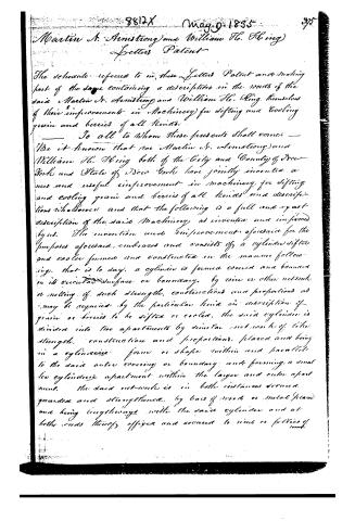
The schedule referred to in these Letters Patent and making part of the same containing a description in the words of the said Martin A. Armstrong and William H. King themselves of their improvement in Machinery for sifting and cooling grain and berries of all kinds.
To all to whom these presents shall come —
Be it known that we Martin A. Armstrong and William H. King both of the City and County of New York and State of New York have jointly invented a new and useful improvement in machinery for sifting and cooling grain and berries of all kinds and description whatsoever and that the following is a full and exact description of the said Machinery as invented and improved by us. The invention and improvement aforesaid for the purposes aforesaid, embraces and consists of a cylinder sifter and cooler formed and constructed in the manner following, that is to say, a cylinder is formed covered and bounded in its circular surface or boundary, by wire or other network or netting of such strength, construction and proportions as may be required by the particular kind or description of grain or berries to be sifted or cooled, the said cylinder is divided into two apartments by similar net works of like strength, construction and proportions, placed and being in a cylindrical form or shape within and parallel to the said outer covering or boundary and forming a smaller cylindrical apartment within the larger and outer apartment. The said net works is in both instances secured, guarded and strengthened, by bars of wood or metal placed and being lengthways with the said cylinder and at both ends thereof affixed and secured to rims or felloes of wood.
Page 3.
or metal which protect the ends edges of the said network respectively, and to which bars the said network is secured. The extremities or ends of the said outer apartment of the said cylinder are closed or bounded by circular end plates or pieces of wood or metal of the same diameter as the said cylinder from the middle of which said end plates respectively a circular piece is cut out of sufficient size and dimensions to leave entirely open the ends or extremities of the said inner apartment of the said cylinder. The said end plates are strengthened, guarded and secured respectively by arms of wood or metal, crossing each other at the centre of each of the said end plates respectively where they are secured in journals or bearings of wood or metal, and which arms respectively run and extend at the ends thereof to the circumference of the said end plates. On the outer circular surface or boundary of the said outer apartment of the said cylinder an open space is left being the entire space between two of the bars which secure the said outer network as aforesaid, the sides of which last mentioned two bars next to and bounding the said open space are so grooved that a cover made of wood or metal or if not wood cased in wood or metal may slide freely and securely in and between the said grooved sides of the said bars thus forming an opening to the said outer apartment of the said cylinder, which may be closed or opened at pleasure. The said inner apartment of the said cylinder is occupied by a fan called or distinguished as the upper fan, composed of a shaft to which are affixed and secured at alternate right angles to each other, four thin plates of wood or metal of such length and depth as will permit them to revolve upon the said shaft freely and with as much effect as may be within the said inner apartments of the said cylinder. The said cylinder
Page 4.
8812X 397
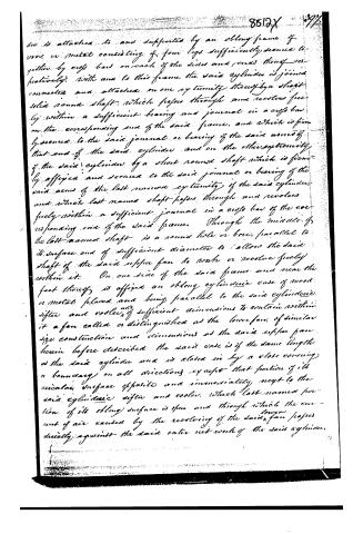
is attached to and supported by an oblong frame of wood or metal consisting of four legs sufficiently secured together by cross bars on each of the sides and ends thereof respectively. With and to this frame the said cylinder is joined connected and attached on one extremity thereof by a short solid round shaft, which passes through and revolves freely within a sufficient bearing and journal in a cross bar on the corresponding end of the said frame, and which is firmly secured to the said journal or bearing of the said arm of that end of the said cylinder and on the other extremity of the said cylinder by a short round shaft which is firmly affixed and secured to the said journal or bearing of the said arm of the last named extremity of the said cylinder, and which last named shaft passes through and revolves freely within a sufficient journal in a cross bar of the corresponding end of the said frame. Through the middle of the last named shaft is a round hole or bore, parallel to its surface and of sufficient diameter to allow the said shaft of the said copper fan to work or revolve freely within it. On one side of the said frame and near the feet thereof is affixed an oblong cylindrical case of wood or metal placed and being parallel to the said cylindrical sifter and cooler, of sufficient dimensions to contain within it a fan called or distinguished as the lower fan, of similar size construction and dimensions as the said copper fan herein before described. The said case is of the same length as the said cylinder and is closed in by a close covering or boundary on all directions except that portion of its circular surface opposite and immediately next to the said cylindrical sifter and cooler, which last named portion of its oblong surface is open and through which the current of air caused by the revolving of the said lower fan passes directly against the said outer network of the said cylinder.
Page 5.
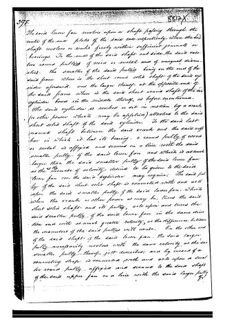
The said lower fan revolves upon a shaft passing through the centre of the end plates of the said case respectively where the said shaft revolves or works freely within sufficient journals or bearings. To the ends of the said shaft out side the said case, two round pulleys of wood or metal and of unequal diameters, the smaller of the said pulleys being on the end of the said frame where is the short round solid shaft of the said cylinder, and the larger thereof at the opposite end of the said frame where is the said short round shaft of the said cylinder bored in the middle thereof, as before mentioned.
The said cylinder is rocked or set in motion by a crank (or other power which may be applied) attached to the said short solid shaft of the said cylinder. To the said last named shaft between the said crank and the said cylinder in which it has its bearing, a round pulley of wood or metal is affixed and secured on a line with the said smaller pulley of the said lower …
Page 6.
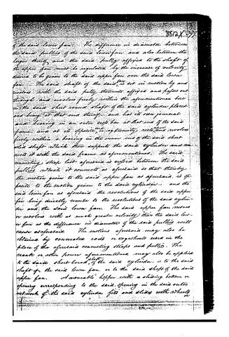
of the said lower fan. The difference in diameter between the said pulleys of the said lower fan and also between the larger thereof and the said pulley affixed to the shaft of the upper fan must be regulated by the increase of velocity desired to be given to the said upper fan over the said lower fan. The said shaft of the said fan is set in motion by and revolves with the said pulley thereunto affixed and passes out through and revolves freely within the aforementioned bore in the said short round shaft of the said cylinder placed and being at that end thereof, and has its own journal and bearing in an outer cross bar at that end of the said frame, and at its opposite or extremity rests and revolves freely within a bearing in the inner end of the said short solid shaft which then supports the said cylinder and connects it with the said frame as aforementioned. The said connecting straps last aforesaid is affixed between the said pulleys which it connects as aforesaid so that thereby the motion given to the said upper fan as aforesaid, is opposite to the motion given to the said cylinder, and the said lower fan as aforesaid the revolutions of the said upper fan being directly reverse to the revolutions of the said cylinder and the said lower fan. The said upper fan moves or revolves with as much greater velocity than the said lower fan as the difference in diameter of the said pulleys will cause aforesaid. The motions aforesaid may also be obtained by connected rods or cogwheels used in the place of the aforesaid connecting straps and pulleys. The crank or other power aforementioned may also be applied to the said short-bored shaft of the said cylinder, or to the said shaft of the said lower fan, or to the said shaft of the said upper fan. A moveable hopper with a sliding bottom or opening corresponding to the said opening in the said outer network of the said cylinder fits and slides with wheels or
Page 7.
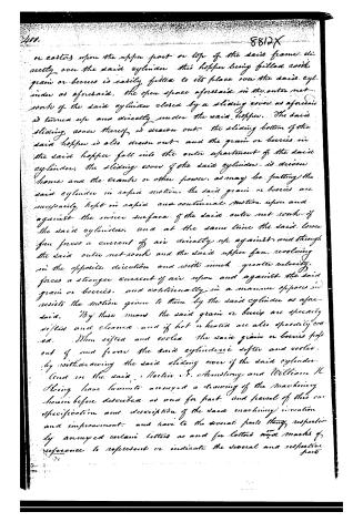
or castors upon the upper part or top of the said frame directly over the said cylinder this hopper being filled with grain or berries is easily fitted to its place over the said cylinder as aforesaid, the open space aforesaid in the outer net-work of the said cylinder closed by a sliding cover as aforesaid is turned up and directly under the said hopper. The said sliding cover thereof is drawn out. The sliding bottom of the said hopper is also drawn out and the grain or berries in the said hopper fall into the outer apartment of the said cylinder, the sliding cover of the said cylinder is driven home and the crank or other power, as may be putting the said cylinder in rapid motion, the said grain or berries are necessarily kept in rapid and continual motion upon and against the inner surface of the said outer net-work of the said cylinder, and at the same time the said lower fan forces a current of air directly up against and through the said outer net-work and the said upper fan, revolving in the opposite direction and with much greater velocity, forces a stronger current of air upon and against the said grain or berries, and continually in a manner opposed and resists the motion given to them by the said cylinder as aforesaid. By this means the said grain or berries are speedily sifted and cleaned and if hot or heated are also speedily cooled. When sifted and cooled the said grain or berries fall out of and from the said cylindrical sifter and cooler, by withdrawing the said sliding cover of the said cylinder.
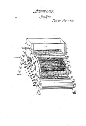
And we the said Martin F. Armstrong and William H. King have herewith annexed a drawing of the machinery herein before described as one for part, and several of this our specification and description of the said machinery invention and improvement, and have to the several parts thereof respectively annexed certain letters as and for letters and marks of reference to represent or indicate the several and respective parts
Page 8.
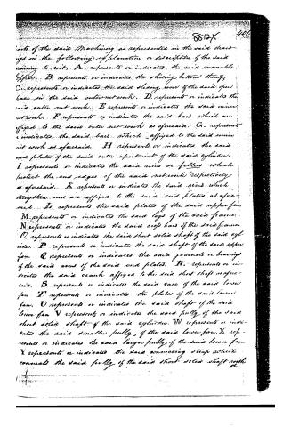
parts of the said machinery as represented in the said drawings in the following explanation or description of the said raising to suit. A. represents or indicates the said movable upper. B. represents or indicates the sliding bottom thereof. C. represents or indicates the said sliding cover of the said open face in the said outer network. D. represents or indicates the said outer network. E. represents or indicates the said inner network. F. represents or indicates the said bars which are affixed to the said outer network as aforesaid. G. represents or indicates the said bars which are affixed to the said inner network as aforesaid. H. represents or indicates the said end plates of the said outer apartment of the said cylinder. I. represents or indicates the said rims or fells which protect the end edges of the said networks respectively as aforesaid. K. represents or indicates the said arms which strengthen and are affixed to the said end plates as aforesaid. L. represents the said plates of the said upper fan. M. represents or indicates the said legs of the said frame. N. represents or indicates the said cross bars of the said frame. O. represents or indicates the said short solid shaft of the said cylinder. P. represents or indicates the said shaft of the said upper fan. Q. represents or indicates the said journals or bearings of the said arms of the said end plates. R. represents or indicates the said crank affixed to the said short shaft as aforesaid. S. represents or indicates the said case of the said lower fan. T. represents or indicates the plates of the said lower fan. U. represents or indicates the said shaft of the said lower fan. V. represents or indicates the said pully of the said short solid shaft of the said cylinder. W. represents or indicates the said smaller pully of the said lower fan. X. represents or indicates the said larger pully of the said lower fan. Y. represents or indicates the said connecting strap which connects the said pully of the said short solid shaft with the
Page 9.
the said smaller pully of the said lower fan as aforesaid.
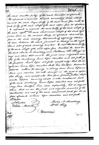
D represents or indicates the said connecting strap which connects the said larger pully of the said lower fan with the said pully of the said shaft of the said upper fan as aforesaid.
E represents or indicates the said pully of the said shaft of the said upper fan, the said short round shaft of the said cylinder bored in the middle thereof as aforesaid does not appear on the said drawing but would if appearing thereon be seen between the said journal or bearing on the right hand side of said drawing marked Q. and the said pully of the said shaft of the said upper fan marked E. and we the said Martin A. Armstrong and William H. King do say and claim that we are the joint and original inventors of the machinery herein before described and set forth for the purposes herein before set forth except only that the said cylinder herein before described hath been heretofore known and patented without the opening or sliding cover herein before mentioned and described but with openings in the ends or extremities thereof and except also that fans, frames, pulleys, shafts, cranks, levers, connecting straps or other component parts of the said machinery herein before described and set forth, may have heretofore been used separately; but we say and claim that we are the joint and original inventors of the combination and uses of the said component parts for the purposes aforesaid as herein before described and set forth.
Witnesses
A. Tucker
Elisha Marills
Martin A. Armstrong
Wm H. King
Exh.
M.H.
2805
Published accounts: journal notice
Notice in the monthly list of patents
Journal of the Franklin Institute, new ser., vol. 16 (1835), p. 71 · View the page
309. Cooking stove--John C. Kolbe, city of Philadelphia,
Published accounts: journal notice
Notice in the monthly list of patents, with remarks
Journal of the Franklin Institute, new ser., vol. 16 (1835), p. 389 · View the page
14. For a Machine for sifting and cooling Grain and Berries; Martin N. Armstrong, and William H. King, City of New York, May 9.
Remarks. Two wire screens, an inner and an outer, are placed concentrically, and revolve upon horizontal axles. The grain, &c. to be cooled or sifted, is admitted between the two cylinders by a door extending along the outer cylinder. Within the inner cylinder there is a re volving fan, and another below the outer cylinder, which conjointly blow upon the article contained between the two screens. The description is extremely verbose, partaking largely of " the said" and "aforesaid" style of a special pleader; we should have been spared much trouble had the specification been sifted, or winnowed, and the grain only deposited in the patent office. The driving machinery consist of bands and wheels, and possesses no novelty. We give the claim. "And we, the said Martin N. Armstrong, and William H. King, do say and claim, that we are the joint and original inventors of the machinery hereinbefore described and set forth, for the purposes hereinbefore set forth, except only that the said cylinder hereinbefore described, hath been heretofore known and patented, without the opening or sliding cover hereinbefore mentioned and described, but with openings in the ends or extremities thereof; and except also that fans, frames, cases, pulleys, shafts, cranks, hoppers, connecting straps, or other component parts of the said machinery, hereinbefore described and set forth, may have heretofore been used separately; but we say and claim, that we are the joint and original inventors of the combination and uses of the said component parts, for the purposes aforesaid, as hereinbefore described and set forth." It may be worth enquiry whether "the said cylinder" which "hath been heretofore known and patented," but with openings at the ends instead of on one side, if not free to be used by the patentee, would become so by merely changing the place of opening.
Published accounts: journal notice
Notice in the monthly list of patents, with remarks
Journal of the Franklin Institute, new ser., vol. 16 (1835), p. 390 · View the page
This is called a double reflecting cooking stove. The body of it is to be a metallic box, which is to stand upon four legs: its appearance in the drawing very nearly resembles that of a double desk, the two sloping sides being hinged in the same manner, in order to give access to the interior; the form of the bottom is the same with that of the top, two of its sides being made to slope in the same manner, for the purpose of reflecting the heat upon the articles to be cooked. The fire place passes along the middle of the box, occupying the space which would be under the horizontal part in a double desk. This horizontal part is open, for the purpose of admitting pans, kettles, &c. to stand over the fire, and from it also ascends the smoke flue. The box, or stove, which contains the fire, is made to lift out, together with its grate, ash pit, &c. Along one of the chambers of the box, there is a spit, and into the other may be put articles to be baked, &c. The claim made is to the particular arrangement and construction of this stove, for cooking by reflected heat, but not to the cooking by reflection, excepting in an apparatus constructed like that described. 18. For a Thrashing Machine; Stapleton C. Sneed and Wm. B. Carpenter, Albemarle county, Virginia, May 9.
Remarks. The manner of fastening the spikes into the wood of the cylinder and concave appears to be the thing which these patentees suppose to be an improvement, although they have not said so distinctly, or made any claim; but in all other points this machine is like a hundred others.
About this record
- Patentee
- DATAMP
- Date
- the Name and Date index of patents, DATAMP, USPTO records
- Invention
- DATAMP
- Listed in
- the Name and Date index of patents, DATAMP, USPTO records, Jim Shaw's X-patent list, the Journal of the Franklin Institute, Burke's List of Patents (1847)
- Burke's 1847 Patent Office list gives the same patent.