

Drawings and documents
USPTO scan
The patent as scanned by the USPTO
-
 Page 1
-
 Page 2
-
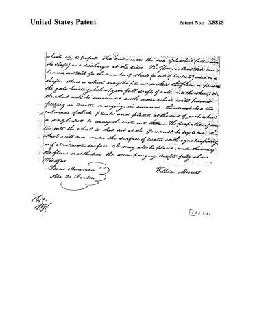 Page 3


U.S. Patent and Trademark Office · Google Patents
Show the transcription Hide (599 words)
Machine transcription (LightOnOCR) of the pages as scanned by the USPTO, most of them the handwritten copies made when the records were restored after the 1836 fire. Not checked; it can misread handwriting, so compare it with the scan.
Page 2.
United States Patent
Patent No.: X8825
William J. Morell
Letters Patent
The Schedule refers to in these Letters Patent and making part of the same containing a description in the words of the said William Morell himself of his improvement in the construction of a water wheel.
To all to whom these presents shall come:
Be it known that I, William Morell of Randolph in the County of Polage and State of Ohio have invented a new and useful improvement in constructing and making and using a water wheel and that the following is a full and exact description of the construction and operation of the said water wheel as invented or improved by me.
The wheel is formed by shaft and buckets. The shaft is made of a tree large enough to comprise a knob or knobs two feet in diameter, to which the buckets are attached. The remainder of the shaft tapers down to ten inches diameter. Five buckets (or more) form the wheel (or circle). The buckets may be made of wood or metal in a circular form with a square shoulder in the inside near the center (parallel with shaft) also a small notch in the outside to serve as a lock as far as which the adjoining buckets lap on. The buckets three and half inches thick and eleven inches long, four inches of which is attached to the knob leaving six inches for space and one inch at the end opposite the knob of the wheel to support to the adjoining buckets. There to be cut in each bucket six inches in length parallel with the shaft and two and half inches wide at the inside and two inches wide at the outside and out in a circular form so as to give the water an easy passage. The buckets are to be fixed to the knob and a band around each end of the buckets (¾ inch wide at the end the water enters). The wheel may be made with one or more sets of buckets or wheels on a shaft. It operates on the reaction principle and may be used on a perpendicular or horizontal shaft or a shaft sloping to any degree that may be necessary to accommodate the machine which.
Page 3.
United States Patent
Patent No.: X8825
which is to propel. The water enters the six of the wheel (all around the shaft) and discharges at the sides. The floor or Penstock must be made suitable for the number of wheels (or sets of buckets) used on a shaft. And a wheel may be placed within the floor or penstock. The gate hoisting below (give full draft of water into the wheel) the wheel will be surrounded with water which will prevent freezing in winter or drying in summer. There must be a tunnel made of thick plank and placed at the end of each wheel or set of buckets to convey the water into them. The proportion of water into the wheel to that out at the ifues must be six to one. This wheel will run under the surface of water with equal rapidity as if above water surface. It may also be placed under the end of the floor or at the side the accompanying drafts fully show.
Witnesses:
Isaac Menniman
Asa W. Harson
William Merrell
T. H.
1885
[598 10 2]
About this record
- Patentee
- DATAMP
- Date
- the Name and Date index of patents, DATAMP, USPTO records
- Invention
- DATAMP
- Listed in
- the Name and Date index of patents, DATAMP, USPTO records, Jim Shaw's X-patent list, Burke's List of Patents (1847)
- Burke's 1847 Patent Office list gives the same patent.