

Drawings and documents
USPTO scan
The patent as scanned by the USPTO
-
 Page 1
-
 Page 2
-
 Page 3
-
 Page 4
-
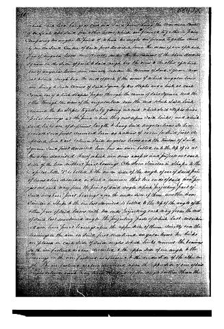 Page 5
-
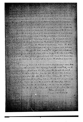 Page 6


U.S. Patent and Trademark Office · Google Patents
Show the transcription Hide (771 words)
Machine transcription (LightOnOCR) of the pages as scanned by the USPTO, most of them the handwritten copies made when the records were restored after the 1836 fire. Not checked; it can misread handwriting, so compare it with the scan.
Page 1.
E. A. & A. Hibbard.
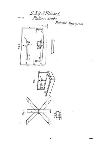
8847X Platform Scales. Patented May 29, 1835.
Fig 2.
Fig 1.
Fig 3.
Fig 4.
Page 2.
May 29, 1835
Elias A. Hittman & A. Hittman, Smeadbury, Vermont
Sellers Patent
The following is a description of the invention of Elias A. Hittman and A. Hittman, of Smeadbury, Vermont, for an improved method of making paper.
The invention consists in the use of a certain combination of materials and processes which are described in detail below.
The process begins with the preparation of a pulp from wood or other fibrous material. This pulp is then mixed with a solution of alum and iron salts, which are known to improve the strength and durability of the paper.
Next, the pulp is spread onto a moving belt of wire mesh, which allows the excess water to drain away. The wet pulp is then pressed to remove more moisture and to form a uniform sheet.
After pressing, the sheet is dried in a heated chamber to remove any remaining moisture. The dried sheet is then cut into the desired size and shape.
The use of alum and iron salts in the pulp mixture significantly improves the quality of the paper, making it more resistant to tearing and more suitable for writing on.
This method of making paper is more efficient and cost-effective than traditional methods, and it produces a higher quality product.
In conclusion, the invention of Elias A. Hittman and A. Hittman represents a significant advancement in the field of paper manufacturing. It is hoped that this invention will be widely adopted and will benefit the paper industry as a whole.
Page 5.
which said bars hang or each end in a joint being the common center of the said bars and from other bars which are formed together in pairs.
Comparing the angles the joints of which the angles are placed together directly under said center of said joint described from the arms of one of which pair of angular bars run directly near the two corners of the said square square on the side opposite to said right by the arms to the other of which pair of angular bars run directly near the corner of said square near at said right by the ends of each of the arms of which angular bars are hung to said corner of said square by two staples and a link at each corner one of which staples passes through the corner of said square and the other through the arm of the angular bar near the end which said link connects the two staples together by going into each which said staples have their bearings at the joints where they rest upon said links; and which said links are of sufficient length to hang said angular bars so low beneath said first described bars as to draw of room for said first described bars to act between said angular bars and the tension of said square said first described bars has an iron bolt on the top of it at the above described head of which iron arms except and project out each side of the bars without first bearings.
On the other similar in shape to the opposite letter T is bolted to the under side of the angle of one of said pair of bars above described in such a manner that the ends of said iron project out each way from the point of said angle which projecting parts of said iron have first bearings upon the under side of them and the iron similar in shape to the one last described is bolted to the top of the angle of the other pair of said bars with the ends projecting each way from the end of said last mentioned angle the projecting parts of which last mentioned iron have first bearings upon the upper side of them directly over the bearings on the iron on said first mentioned angular bars the links are placed on each side of said angles which links connect the bearings on the iron fastened to one described to the upper side of one angle to the bearings on the iron fastened as aforesaid to the under side of the other angle.
The iron fasteners are here described upon the opposite side of one of the angles of bars each way from the line of the angle to the other then the
Published accounts: journal notice
Notice in the monthly list of patents
Journal of the Franklin Institute, new ser., vol. 16 (1835), p. 71 · View the page
293. Weighing scales. Elias A. and A. Hibberd, Lunenburg, Vermont,
Published accounts: journal notice
Notice in the monthly list of patents, with remarks
Journal of the Franklin Institute, new ser., vol. 16 (1835), p. 401 · View the page
43. For a Double Lever Scale; Elias A. and Asa Hibberd, Lunenberg, Essex county, Vermont, May 29.
Remarks. This is a platform balance, in which the arrangement of the levers differs in some points from any which has preceded it, but not in a way which appears likely to give greater accuracy to the instruVOL. XVI.-No. 6. - DECEMBER, 1835. 51 ment; a thing, indeed, hardly to be desired. A scale is hung upon the steelyard, in such a situation as to weigh a hundred fold, and a movable poise gives the intermediate weights. The claim would occupy more than a page, and we cannot, therefore, find room for it; it includes the whole description of the machine, and extends to many things which have been before used.
About this record
- Patentee
- DATAMP
- Date
- the Name and Date index of patents, DATAMP, USPTO records
- Invention
- DATAMP
- Listed in
- the Name and Date index of patents, DATAMP, USPTO records, Jim Shaw's X-patent list, the Journal of the Franklin Institute, Burke's List of Patents (1847)
- The Franklin Institute's journal spells the name differently.
- Burke's 1847 Patent Office list gives the same patent.