

Drawings and documents
USPTO scan
The patent as scanned by the USPTO
-
 Page 1
-
 Page 2
-
 Page 3
-
 Page 4
-
 Page 5
-
 Page 6
-
 Page 7


U.S. Patent and Trademark Office · Google Patents
Show the transcription Hide (2,522 words)
Machine transcription (LightOnOCR) of the pages as scanned by the USPTO, most of them the handwritten copies made when the records were restored after the 1836 fire. Not checked; it can misread handwriting, so compare it with the scan.
Page 1.
8849X
J. Kirkpatrick.
Steam-Engine Valve-Gear.
Patented May 29, 1835.
AM. PHOTO-LITHO. CO. N.Y. (OSBORNE'S PROCESS)
Page 2.
John Kirkpatrick
Letters Patent
No. 525
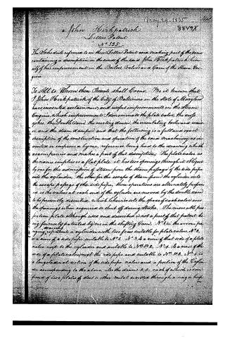
The Schedule referred to in these Letters Patent and making part of the same containing a description in the words of the said John Kirkpatrick himself of his improvement in the Boilers, Valves and Gears of the Steam Engine.
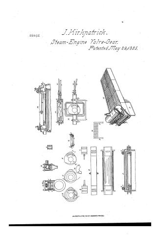
To All to Whom these Presents shall Come, Be it known that I John Kirkpatrick of the City of Baltimore in the State of Maryland have invented certain new and useful improvements in the Steam Engine, which improvements I denominate the plate valve, the orophy, the Double Band, the reacting drum, the circulating boiler and receiver, and the steam damper, and that the following is a full and exact description of the construction and operation of the said machinery as invented or improved a by me, reference being had to the drawing which accompanies and makes a part of this description. The plate valve as the name implies is a flat plate, it has two openings through it obliquely one for the admission of steam from the steam passage of the side pipe into the cylinder, the other for the escape of steam from the cylinder into the escape passage of the side pipe, these operations are alternately performed as the valves at each end of the cylinder are moved by the double band to be presently described, which likewise sets the space of each valve over the openings when required to shut off during stroke. The movable projection plate although used and described is not a part of this patent being formerly patented by me in the shifting band. No. 1 in the annexed drawing represents a cylinder with two faces suitable for plate valves. No. 2 is a view of a side pipe suitable to No. 1. No. 3 is a view of that side of a plate valve next to the cylinder and suitable to No. 1. No. 4 is a view of the side of a plate valve next the side pipe and suitable to No. 1. No. 5 is a longitudinal section of the side pipe, valve and a portion of the cylinder corresponding to the above, also the drums &c. each of which is composed of two plates of steel or other metal erected through a ring or hoop.
Page 3.
on the outer edges and connected with the steam passage of the side pipe f. No 5. the self-balancing principle being applied without a piston by the elasticity of the plate, greater elasticity can be obtained by making the sides of the drum in the form shown at Nos. 11 & 12. The outer edges may be secured firmly by the inner ones turned and ground to fit steam tight, or fast to together with joints; k, is the exhaust passage of the side pipe. No 6. is a view of that side of the Cam used in exhausting without the half stroke plate. The dark part represents the recess in which the plate slides. The projection b, m, n, m' moves in the space a. No. 6. No 7 represents that side of the cam which alternately opens the valves at each end of the cylinder for the admission of steam. No 8 is a side view of the whole cam, with the half stroke plate attached which is half the thickness of the exhaust of the cam, the projection being of the same thickness reaches entirely across that side of the cam. The line left at No. 6 and No. 7, compared with No. 9 sufficiently illustrate the formation of No. 8. - e. e. No. 9 is an edge view of No. 6. and f. f. No. 9 is an edge view of No. 7. No. 9 is an edge view of the whole double cam No. 8. which requires 2 cycles as shown at No. 14, & 15. they on each other and are acted upon alternately by the points of each side of the double cam. The point g, No. 8. opens to let on steam, the point h, shuts off during the stroke, and the point i, exhausts. This valve then remains stationary, till the other performs similar operations, when it in turn remains stationary, and the first commences as before, and so they continue onward alternately changing operations. No 10 is a projection of the cylinder and pipe valves and guides, f, is the side passage. k, the exhaust passage. l, the valve, m, the cross bar, n, the guides. o, the conical plate which is pressed against the drum by the action of the screw, on the column p, p, through the cross bar m, by which means the degree of pressure on the valve is regulated. No 13 is a perspective view of No. 6. with the necessary appendances attached, g, is one of the two rods that hold the weight of the side pipe when vertical and prevent it from moving longitudinally when horizontal. s, s, are the valve rods and s. s. the holes in the guiding plates through which the movements of the valve are observed when at work. All other parts of 13 are explained by the corresponding parts of No. 12. and No. 6. See No. 14 & 15. t. t. t. t.
Page 4.
represents the four corners of the side box upon which the two fellow blocks O. O. are cast solid; c c. c. are the two cams of the one c c. c. the same case. N° 16 is a view of an elbow pipe and stuffing box that may sometimes be necessary to prevent the side pipe from pressing too forcibly against the guides. Here is the width of the opening added to the difference between the width of the opening and that of the valve space (which is now the opening in the cylinder when shut off during the stroke) is the whole distance through which the valve is required to move; in opening the whole distance is passed through at one move, but in returning one half the distance is first passed through to shut off during the stroke and the remainder at proper time to exhaust. This motion is particularly applicable to one modification for the condensing engine of the self-balancing slide valve formerly patented by me. N° 17 and 18, are different views of a boiler which I call a circulating Boiler and which may be composed of one or more regular parallels or other formed longitudinal vessels, exposing to the action of the fire the whole surface excepting the ends which on account of convenience in making may be cast, the forward end having two pipes cast on it, one at the top for the steam to pass out at, and one at the bottom for the water to pass in at, the back head has one hole cast in it at the bottom, into which a scraper or brush can be passed to clean out the boiler. N° 17 is a perspective view of a large circulating Boiler composed of ten small ones, connected with a circulating receiver X. N° 18, is a transverse section of N° 17, at the furnace and under the receiver; the letters of designation are common to both. y. y. represents the logs of the outside parallels which form the sides of the furnace and are necessary only on board of boats to avoid weight; the intermediate ones form the top and have sufficient space left between them for the passage of flame which is conducted into the chimney at the back end. The size of the receiver should be of such proportion to that of the boilers and of the surface they expose that the water which fills the boilers only when cold will fill about one half the receiver in addition when at a proper temperature to generate a continual supply of steam for the Engine. These boilers having the greatest exposure of surface in proportion to the quantity of water they contain and being subjected to the
Page 5.
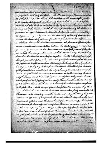
most intense heat, will require the capacity of the receiver to be greatest in proportion to that of the boilers. The Boilers being all connected at the top of the pipes &c. with the top of the receiver &c. the steam passes freely into the receiver taking with it a portion of water which immediately settles down and passes back in to boilers by the pipes a, a, which connect the lower part of the receiver with the lower part of each of the boilers and preserves an equilibrium between the boilers and receiver, excepting the difference in gravity, between the ascending column of steam and water and the descending column of water only added to the difference in altitude between the boilers and receiver, the former difference preserves a continual circulation between the boilers and receiver while generating steam, and the latter preserves a supply of water to each of the boilers, while there is any in the receiver which should always be about half full when the steam is at a proper height. The stay bolts which are to pass through parallel of this boiler should be of sufficient strength to bear the pressure to be applied without straining (which may be tested by a hydraulic apparatus) they ought to be put on without thimbles before the sides of the parallel are rivetted at the edges, having shoulders to receive the sheet, they should be small and numerous as by that means the sheet may be thinner and the rivetting more easily done cold, besides the advantage of a hole passing more readily through a thin sheet, it is less apt to blister than a thick one, and as nearly the whole surface is exposed to the fire, there is little danger of rust; but if thimbles are used they should have holes in them to admit the water to circulate freely round the bolts. The same rules should govern the builder respecting the strength of material and exposure of surface in this as in other Boilers, where the same pressure is applied and the same kind of fuel made use of. Short boilers constructed for burning coal may have the receiver made as represented in the accompanying drawings. But for long Boilers calculated to burn wood as in board of boats the receiver can be made about the length of the Boilers and set longitudinally so that an arrangement of engine most common in high pressure boats, the steam being taken out of the back end. The flame may allowed to return under the receiver.
Page 6.
receiver after a sufficient supply of water has been forced into it by the action of the fire upon the water in the Boilers, until then the flame must be let into the chimney by means of a separate flue without coming in contact with the receiver, which must always be done when the water is low in the receiver from any cause, it is only in land engines that much benefit can be expected from using the flame returning under the receiver, the weight of a separate flue and casing being too great for Boats. In setting such Boilers it is necessary to place the end connected with the receiver highest that the steam may pass from the boilers into the receiver as fast as it is generated. The casing or brick work should come close to the bottom of the boilers to confine the flame principally between them; the top to be covered with brick work; or the upper parts of the Boilers may be so formed as to meet, the boilers are cleaned out at an opening in the lower part of the back head, which end being the lowest is favourably situated for that purpose by opening one at a time and pumping water into the receiver, a current will be sent through such at such opening (to assist in cleaning). The front of the ash pits is made to shut close and a pipe connected with the lower part of the escape steam pipe leads into it when the engine is stopped and steam escaping, the fire may then be damped or even extinguished by merely shutting the ash pit door. These boilers afford various advantages in the extent of surface exposed, the small quantity of water contained the facility with which they can be constructed, repaired or transported from place to place, the small space which they occupy and the high pressure which they will bear compared with the low pressure boilers now in use. Boilers have been to some extent used with a fire front connected with the main boiler allowing the water there from to flow in front of the fire, or the boiler has been fed by means of a force pump passing water through the fire front, but by the arrangement adopted by me each of the combined parallel Boilers becomes a generator, the whole surface of which may be exposed to the action of the fire as completely as are the tubes of tubular boilers, whilst by attaching a receiver for the steam, and connecting therewith and with the Boilers two pipes open
Page 7.
ating upon the principle herein explained the steam and water are of-
fectually separated. And the parallel boilers are each kept full of water
which continually flows into them through the lower pipes while their
inclined positions facilitate that operation. What I claim in this
part is forming a boiler by the combination of any number of what I
have called parallel boilers which are placed in an inclined posi-
tion to promote the passage of steam out, and the flow of water into
them and the placing above them a receiver connected by means of a
common steam tube with the upper edges of the parallel boilers and
by means of a second or water tube with their lower edges for the pur-
poses herein set forth. I also claim the manner of connecting the waste
steam pipe with the ash pit for the purpose of damping or extinguish-
ing the fire varying the particular arrangement of the respective parts
in any way (which I may deem proper) whilst I do not depart from the
general principle of operation. What I claim in the valve and
herein described is the particular arrangement of the openings of the
valve as shown at fig 5, and the parts connected with it, the par-
ticular construction of the double cam, with its manner of action
through the medium of the propylaxis herein described and the adjustment
by which it is adapted to the purpose intended, the reacting drum,
applied upon the principles and for the purpose described, together with
such modifications and variations in the form and arrangement
of these parts which are substantially in accordance with the gen-
eral principle
John Heilpatrick
Sam Stettinius
R R Burr
(Patented May 29, 1855) (2780 Words)
the Additional Improvements No. 1, granted
6th day of October 1857 - Vol. 1, page 1 additional Improvements.
(Drawing)
Published accounts: journal notice
Notice in the monthly list of patents
Journal of the Franklin Institute, new ser., vol. 16 (1835), p. 71 · View the page
295. Steam engine. John Kirkpatrick, Baltimore, Md.
Published accounts: journal notice
Notice in the monthly list of patents, with remarks
Journal of the Franklin Institute, new ser., vol. 16 (1835), p. 402 · View the page
45. For improvements in the Boilers, Valves, and Cam, of the Steam Engine; John Kirkpatrick, city of Baltimore, May 29.
Remarks. The specification of this patent will hereafter be published, together with that of some further improvements, which are now nearly completed.
About this record
- Patentee
- DATAMP
- Date
- the Name and Date index of patents, DATAMP, USPTO records
- Invention
- DATAMP
- Listed in
- the Name and Date index of patents, DATAMP, USPTO records, Jim Shaw's X-patent list, the Journal of the Franklin Institute, Burke's List of Patents (1847)
- Burke's 1847 Patent Office list gives the same patent.