

Drawings and documents
USPTO scan
The patent as scanned by the USPTO
-
 Page 1
-
 Page 2
-
 Page 3
-
 Page 4
-
 Page 5
-
 Page 6


U.S. Patent and Trademark Office · Google Patents
Show the transcription Hide (2,120 words)
Machine transcription (LightOnOCR) of the pages as scanned by the USPTO, most of them the handwritten copies made when the records were restored after the 1836 fire. Not checked; it can misread handwriting, so compare it with the scan.
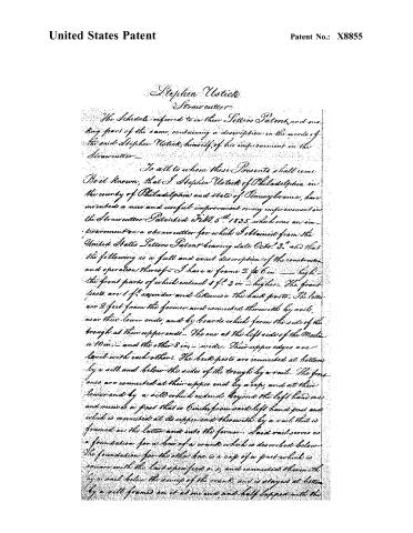
Page 2.
United States Patent
Patent No.: X8855
Stephen Ustick
Strawcutter
The Schedule referred to in these Letters Patent, and making part of the same, containing a description in the words of the said Stephen Ustick, himself, of his improvement in the Strawcutter—
To all to whom these Presents shall come:
Be it Known, that I Stephen Ustick of Philadelphia in the county of Philadelphia and state of Pennsylvania, have invented a new and useful improvement or any improvement in the Strawcutter Patented Feb. 5th 1835, which was an improvement on a strawcutter for which I obtained from the United States Letters Patent bearing date Oct. 23rd and that the following is a full and exact description of the construction and operation thereof:—I have a frame 2 ft. 6 in — high — the front parts of which extend 1 ft. 3 in — higher. The front posts are 1 ft. asunder and likewise the back posts. The latter are 2 feet from the former and connected therewith by rails, near their lower ends, and by boards which form the side of the trough at their upper ends. The one at the left side of the Mallet is 10 in — and the other 8 in — wide. Their upper edges are level with each other. The back posts are connected at bottom by a sill and below the sides of the trough by a rail. The front ones are connected at their upper end by a cap, and at their lower end by a sill which extends beyond the left hand one and receives a post that is 6 inches from said left hand post and which is connected at its upper end therewith by a rail that is framed on the latter and into the former. Said rail serves as a foundation for a box of a crank which is described below. The foundation for the other box is a cap of a post which is square with the last specified one, and connected therewith by a rail below the sweep of the crank and is stayed at bottom by a sill framed on it at one end and half lapped with the
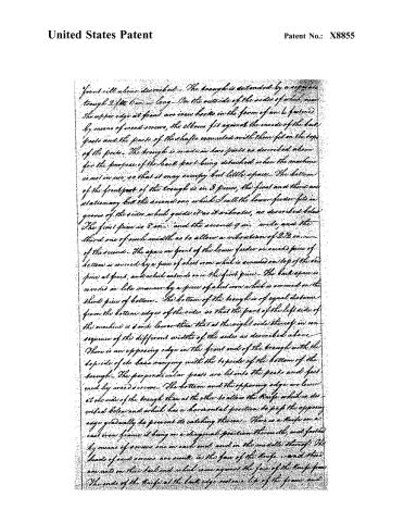
Page 3.
United States Patent
Patent No.: X8855
front will alone described. The trough is extended by a separate trough 2 ft. 6 in. — long. On the outside of the sides of which, near the upper edge at front are iron hooks in the form of an L fastened by means of wood screws, the elbows fit against the inside of the back posts and the parts of the shafts connected with them fit in the top of the posts. The trough is made in two parts as described above for the purpose of the back part being detached when the machine is not in use, so that it may occupy but little space. The bottom of the front part of the trough is in 3 pieces, the first and third are stationary but the second one, which I call the lower feeder fits in grooves of the sides which guide it as it vibrates, as described below. The first piece is 8 in. and the second 9 in. wide, and the third one of such width as to allow a vibration of 2½ in. — of the second. The space in front of the lower feeder or said piece of bottom is covered by a piece of sheet iron which is screwed on top of the said piece at front, and which extends over the first piece. The back space is covered in like manner by a piece of sheet iron which is screwed on the third piece of bottom. The bottom of the trough is of equal distance from the bottom edges of the sides so that the part of the left side of the machine is 8 in. lower than that at the right side thereof, in consequence of the different widths of the sides as described above. There is an opposing edge in the front end of the trough with the top side of its base ranging with the top side of the bottom of the trough. The perpendicular posts are let into the posts and fastened by wood screws. The bottom and the opposing edge are lower at one side of the trough than at the other to allow the knife which is described below and which has a horizontal position to pass the opposing edge gradually to prevent its catching thereon. There is a knife on a cast iron frame, it being on a diagonal position thereon, and fastened by means of screws one in each end, and in the middle thereof. The heads of said screws are sunk in the face of the knife, and there are nuts on their tail end which come against the face of the knife frame. The ends of the knife at the back edge rest on a lip of the frame, and
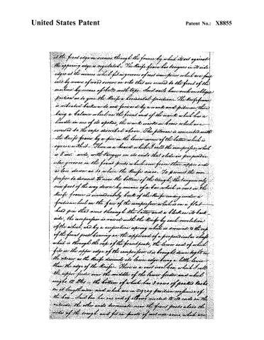
Page 4.
United States Patent
Patent No.: X8855
at the front edge or screws through the frame by which it is set against the opposing edge is regulated. The knife frame has tongues in its side edges at the corners which fit in grooves of cast iron pieces which are fastened by means of wood screws on rails that are secured to the front of the machine by means of bolts with taps. Said rails have such an oblique portion as to give the knife a horizontal position. The knife frame is vibrated backwards and forward by a crank and pitman, there being a balance wheel on the front end of the crank which has a handle in one of its spokes, the crank works in braces which are secured to the caps described above. The pitman is connected with the knife frame by a pin in the lower corner of the latter which is square with it. There is a board which I call the compressor, which is 8 in. wide, with tongues on its ends that slide in perpendicular grooves in the front posts which run from their upper ends as low down as to where the knife rises. To permit the compressor to descend to near the bottom of the trough, the tongues only run part of the way down by means of a bar which is cast in the knife frame is immediately back of the knife coming under a friction wheel on the face of the compressor which is on a flat head pin that runs through the latter and a block on its back side, the compressor is raised with the knife by each revolution of the wheel, and by a serpentine spring which is screwed to the cap of the front post bearing on the upper end of a perpendicular shaft which is through the cap of the front post, the lower end of which fits in the upper edge of the compressor it is brought down tight on the straw as the knife descends its lower edge being a little lower than the edge of the knife. There is a cast iron box, which I call the upper feeder over the middle of the lower feeder and which weighs 12 lbs — the bottom of which has 3 rows of pointed hooks on its lengthwise, and which are in zigzag position crosswise of the box. Said box has one end of elbows riveted to its ends on the outside, the other ends terminate near the front posts above the sides of the trough and fit on pivots of cast iron arms, which are
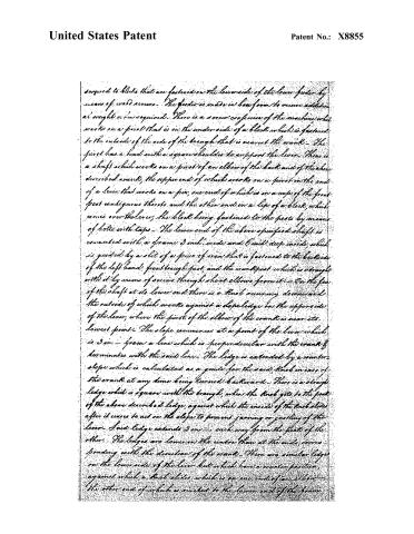
Page 5.
United States Patent
Patent No.: X8855
squared to blocks that are fastened on the lower side of the lower feeder by means of wed screws. The feeder is made in box form to receive additional weight when required. There is a screw crosswise of the machine which works on a pivot that is in the under side of a block which is fastened to the outside of the side of the trough that is nearest the crank. The pivot has a head with a square shoulder to support the lever. There is a shaft which works on a pivot of an elbow of the back and of the above described crank, the upper end of which works on a pivot in the end of a lever that works on a pin, one end of which is in a cap of the front post contiguous thereto and the other end in a lip of a block, which comes over the lever, the block being fastened to the posts by means of bolts with taps. The lower end of the above specified shaft is connected with a frame 3 inch wide and 6 inch deep inside, which is guided by a slit of a piece of iron that is fastened to the backside of the left hand front trough post, and the crank post which is brought with it by means of screws through short elbows from it. On the face of the shaft at its lower end there is a knob occurring downward the outside of which works against a slope ledge on the upper side of the lever, where the pivot of the elbow of the crank is near its lowest point. The slope commences at a point of the lever which is 3 in. from a line which is perpendicular with the crank & terminates with the said line. The ledge is extended by a counter slope which is calculated as a guide for the said knob in case of the crank at any time being turned backward. There is a straight ledge which is square with the trough, when the knob gets to the peak of the above described ledge, against which the inside of the knob slides after it ceases to act on the slope to prevent jarring or jostling of the lever. Said ledge extends 3 in. each way from the peak of the other. The ledges are lower in the center than at the ends, corresponding with the direction of the crank. There are similar ledges on the lower side of the lever but which have a counter position, against which a knob slides which is on one end of an elbow, the other end of which is riveted to the lower end of the frame.
Page 6.
United States Patent
Patent No.: X8855
...which is connected with the crankshaft. By the alternate action of the above described Racks on the latches, there is a vibrating motion given to the lever which causes the feeders above described to vibrate backwards and forwards there being a perpendicular pivot in the end of the lever under the trough that works in a slot, that is crosswise of the trough, of a piece of iron from which there is an elbow running backwards, and which is screwed to the lower feeder. The said pivot is moveable in a slot of the lever by means of a tap on its end under the latter, the part in the slot being flat and having a shoulder above it. This is to regulate the feed of the straw as may be required, by varying the pivot from the fulcrum. The upper feeder is elevated by means of a chain which is connected with it at one end and which runs over a pulley that is in an upright which is supported by a base that is fastened on the top edges of the trough sides being connected at its other end with the inside end of the lever which is connected with the upper end of the crankshaft. The upward motion of the upper feeder and that of the knife are alternate. The forward motion is given to the feeders when the Knife and compressor are up and the backward motion when they are down. Hence when the feeders push the straw forward, the compressor descends and holds the straw tight while the Knife cuts it off and when the Knife and compressor ascend above the straw it is again pushed forward by the feeders and so on in alternate succession.
What I claim as my invention is the cast iron box hung as above described, the arrangement of the machinery, which gives motion to the feeders as above described, and the application of the bar of the Knife frame and the friction wheel which causes the elevation of the compressor as described above. In testimony that the above is my invention I have hereunto set my hand and seal this 12th day of May 1835.
Witnesses
C. H. W. Hartman
Stephen Ustick
Charles Bell
(Witnesses)
Published accounts: journal notice
Notice in the monthly list of patents
Journal of the Franklin Institute, new ser., vol. 16 (1835), p. 71 · View the page
307. Straw cutter.-Stephen Ustick, city of Philadelphia,
Published accounts: journal notice
Notice in the monthly list of patents, with remarks
Journal of the Franklin Institute, new ser., vol. 16 (1835), p. 406 · View the page
57. For an improvement on the Straw Cutter; Stephen Ustick, city of Philadelphia, May 29.
Remarks. This is intended as an improvement of the machine previously patented by Mr. Ustick, and which we noticed in due course; the description of this improvement could not be understood without the drawing, nor would the claim alone give any adequate idea of it.
About this record
- Patentee
- DATAMP
- Date
- the Name and Date index of patents, DATAMP, USPTO records
- Invention
- DATAMP
- Listed in
- the Name and Date index of patents, DATAMP, USPTO records, Jim Shaw's X-patent list, the Journal of the Franklin Institute, Burke's List of Patents (1847)
- Burke's 1847 Patent Office list gives the same patent.