

Drawings and documents
USPTO scan
The patent as scanned by the USPTO
-
 Page 1
-
 Page 2
-
 Page 3
-
 Page 4


U.S. Patent and Trademark Office · Google Patents
Show the transcription Hide (859 words)
Machine transcription (LightOnOCR) of the pages as scanned by the USPTO, most of them the handwritten copies made when the records were restored after the 1836 fire. Not checked; it can misread handwriting, so compare it with the scan.
Page 1.
8883X
J. Page,
Mortising Machine.
Patented June 12, 1835.

A.M. PHOTO-LITHO. CO. N.Y. (OSBORNE'S PROCESS)
Page 2.
Patented June 12, 1835 No. 12
Jonathan Page (June 12, 1835)
Letters Patent 8883X
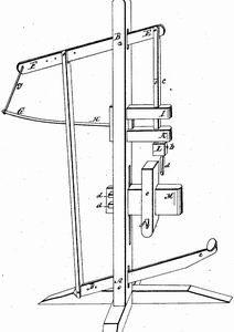
The Schedule referred to in these Letters Patent and making part of the same containing a description in the words of the said Jonathan Page himself of his improvement in the mortising machine. To all to whom these presents shall come Be it known that Jonathan Page of Northampton in the County of Hampshire & State of New-Hampshire have invented a new and useful improvement in the mortising machine and that the following is a full and exact description of the construction and operation of the same as improved by me. The said machine consists of a piece of timber fixed perpendicularly six or seven feet high and six inches wide by three inches thick through which eight inches from the bottom is inserted a lever and another five and three fourths feet above it represented by the lines C.D. and E.F. upon the drawing accompanying this specification. These levers are each about thirty inches long and are fixed at A. and B. by bolts of wood or iron which form their axes. They are connected at D. (and F.) by a shaft of wood one and a fourth by two inches square which is attached by a mortice to the lower lever at a distance of eight inches from its axis, and to the upper one at a distance of eighteen inches. These distances may however be varied and the force produced varied accordingly. To the end E. of the upper lever eight inches from its axis is attached the shaft or handle of the chisel. This is of wood two by one and a fourth inches square at the upper end and thirty four inches long and passes through mortises fitted for the purpose in two pieces of timber one under the other projecting horizontally from the perpendicular timber about ten inches. They are each three inches square and at a distance of three inches apart. The upper one being eighteen inches from the other lever. These pieces serve to guide the shaft.
Page 3.
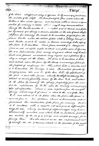
If the chisel. A sufficient play is afforded it by means of a joint near the middle of the shaft. The lower part of it, four inches above the bottom is three inches square, and contains either a round or square socket for receiving a chisel which may be any common chisel having the handle suited to the socket and is turned and fastened by means of a spring or screw inserted in the side of said shaft. A frame for receiving the wood to be mortised projects from the main timber under the chisel fitted with a sliding tenant in said timber so as to be raised or lowered according to the size of the piece to be mortised. Said frame consists of a horizontal piece or rest at right angles to which and fitted upon it by a nut is a perpendicular piece serving as a guard which may be moved back and forward as occasion may require and is fastened by a key or screw at the bottom. The piece to be mortised is held and moved upon the frame by the hands or a carriage fitted for the purpose of confining it. When wheel hubs or similar work is to be mortised the carriage is used. The machine operates by bringing down the end C of the lever C.D. by application of the foot or some other power, whereby the shaft containing the chisel is driven forcibly down by the lever E.F. and restored to its place by means of the spring projecting from the main timber represented by G.H. upon the drawing accompanying this specification. A arm or rod is fastened from the end of the spring, which may be of wood or steel to the end of the bar E.F. and restores it to its place when the foot or other power is removed from C. Your petitioners claims as his invention and improvement the construction of the frame for receiving the piece to be mortised, with a movable rest and guard different from any in use, whereby materials of different sizes may be more conveniently mortised and wheel hubs in particular if all size are mortised by the use of a cheap and simple carriage for confining them. He also claims as an improvement made by himself the use of common chisels in the operation of his machine and
Page 4.
and the cheap and simple construction of the pithole. In testimony that the above and foregoing is a true specification of my said improvement as above described, I have hereunto set my hand this 4th day of May Anno Domini 1835.
Witness
Jonathan Page
Sam Smith
Daniel E Gould
(Drawing)
840 words
8883X 445
[Page]
Published accounts: journal notice
Notice in the monthly list of patents
Journal of the Franklin Institute, new ser., vol. 16 (1835), p. 143 · View the page
333. Mortising machine. Jonathan Page, Henniker, N. H.
DATAMP: illustration
Illustrations from DATAMP
DATAMP (Directory of American Tool and Machinery Patents), via the Internet Archive · Archived DATAMP page
About this record
- Patentee
- DATAMP
- Date
- the Name and Date index of patents, DATAMP, USPTO records
- Invention
- DATAMP
- Listed in
- the Name and Date index of patents, DATAMP, USPTO records, Jim Shaw's X-patent list, the Journal of the Franklin Institute, Burke's List of Patents (1847)
- Burke's 1847 Patent Office list gives the same patent.