

Drawings and documents
National Archives restored drawings: drawing
G.M. Weaver's Patent Drawing for a Machine for Shelling and Grinding Corn

National Archives, Restored Patent Drawings (Record Group 241) · Full-size scan at the National Archives · Catalog record
Show the text on the drawing Hide (93 words)
Words on the drawing as machine-read by the National Archives; not checked. Useful mainly for searching.
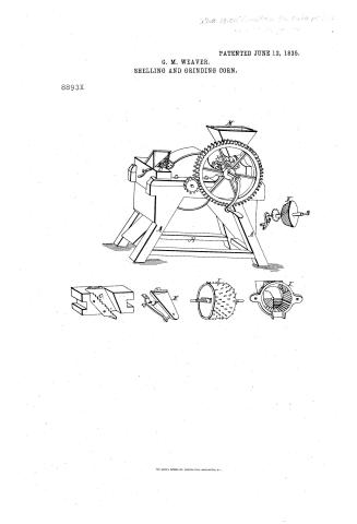
$2- / 83. MILLS. / Grinding Mills. / Cone and Shell. / micrull / CLASSIFICATION / G. O M WEAVER / 8893-7 DIVISION. / Shelling & Grinding Corm / Patented 12 June 1835 / A. Frame / B. Shelling cylinder / C. Feeder-Tlock / D. Grinder / E. Compresser / F'. spring / Co. Gear.Shaft / H. Bevel-gearing / I. shelling Cymmer / K. arinder Neet / DEPARTMENT / L. Grinder- Case / M. Hopper / Strickland / Patent offer Incur 17th 1832 / Made under the directions the com nof haten / Me conformity with achof 3d March 1834 / Mills / ML Sumorth / Commissioner of haten's
National Archives restored drawings: drawing
C. Otis' Patent Drawing for a Churn and Washing Machine

National Archives, Restored Patent Drawings (Record Group 241) · Full-size scan at the National Archives · Catalog record
Show the text on the drawing Hide (72 words)
Words on the drawing as machine-read by the National Archives; not checked. Useful mainly for searching.
83. LAUNDRY. / Vol. 24 /0 / [91] WASHING MACHINESS / Cylinder. / $150 / CLASSIFICATION / 88931/2-X / DIVISION. / C.OTIS / Patented 15 "June 1835 / Churn 8Washi gWashrng.Machine / sections / a. Revolving cylunder or Barrel / b. Trough / C. Flat urngs or buckets / section / stuck / Patent of fice Juno30 the 1843. / Made under the direction of the commynow / of Pateuls in conformity with act g3 "March 1837 / MLSumorth / of Patent
USPTO scan
The patent as scanned by the USPTO
-
 Page 1
-
 Page 2
-
 Page 3
-
 Page 4
-
 Page 5


U.S. Patent and Trademark Office · Google Patents
Show the transcription Hide (1,838 words)
Machine transcription (LightOnOCR) of the pages as scanned by the USPTO, most of them the handwritten copies made when the records were restored after the 1836 fire. Not checked; it can misread handwriting, so compare it with the scan.
Page 1.
PATENTED JUNE 12, 1835.
G. M. WEAVER.
SHELLING AND GRINDING CORN.
8893X

THE NORRIS PETERS CO. PHOTO-LITHO., WASHINGTON, D. C.
Page 2.
8893Y June 12, 1835 301
George M. Meares of Montgomery, Pennsylvania
Letters Patent.
The Reluctant referred to in the Letters Patent, and making part of the same containing a description in the words of the said George M. Meares himself of his improvement in a Machine for shelling and grinding Corn.
To all to whom these presents shall come.
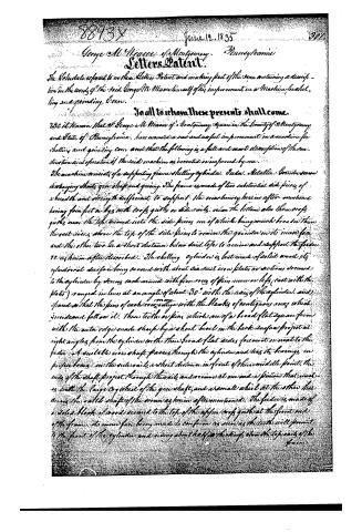
Be it known that I George M. Meares of Montgomery Square in the County of Montgomery and State of Pennsylvania, have invented a new and useful improvement in a machine for shelling and grinding corn and that the following is a full and exact description of the construction and operation of the said machine as invented or improved by me.
The machine consists of a supporting frame, shelling cylinder, teeth, Metallic Cornscrew and discharging shaft, gear shaft and gearing. The frame is made of two substantial side pieces of a breadth and strength sufficient to support the machinery herein after mentioned having four feet or legs with crock quills or side rails, near the bottom also three crock quills near the top turned into the side pieces, one of which being much broader than the rest rises above the top of the side pieces to receive the grinder with its inner face and the other two lie a short distance below said tops to receive and support the feeder as herein after described. The shelling cylinder is best made of solid wood its cylindrical surface being covered with about six or eight iron plates or sections secured to the cylinder by screws each around with numerous of pins, iron or legs (cast with the plates) ranged in lines at an angle of about 30° with the axis of the cylinder, and spaced so that the pins of each row range with the blanks of contiguous rows which precede and follow it. These teeth or pins, which are of a broad flat square form with the outer edges made sharp by a short bevel in the back surface project at right angles from the cylinder with their broad flat sides foremost or nearest to the feeder. A suitable iron shaft passes through the cylinder and has its bearings in proper boxes in the side rails, a short distance in front of their middle point, the ends of the shaft project through the rails and receive at one end a pinion that meshes with the large cog wheel of the gear shaft, and at the other that drives the small shaft of the screw as herein after mentioned. The feeder is made of a solid block of wood secured to the top of the upper crock quill at the front end of the frame, its inner face being made to conform as near as the teeth will permit to the front of the cylinder and rising about half an inch above the top rails of the frame.
Page 3.
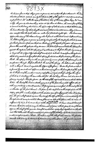
In its inner face a deep oblique gash or groove is cut called the feed channel. The lower shoulder of which extends nearly the whole width of the cylinder and descends at an angle of about 60° with the axis of the latter (that of the rows of pins being 30° more or less). The gash is also something wider at top than at bottom. The inner face of the block is covered with heavy sheet iron. The upper edge of which is over a short distance above the lower shoulder its whole length and is notched or serrated resembling a common saw except that the teeth have no rake but stand straight up. The lower and upper shoulders of the channel may also be faced with sheet iron to prevent wear. The bottom of the gash or groove is entirely occupied by the compressor which is made of a block of wood about one third in thickness of the depth of the gash. Its inner surface or that next the cylinder being concave the better to press and hold the ears of corn against the cylinder whilst operating it is attached to the feeder block by means of a hinge at its upper edge which permits it to vibrate to and from the cylinder which it is made to do by a flat steel spring fastened on the front side of the feeder block. The spring acting on the compressor by means of a pin that passes from the compressor through the feeder block to the end of the spring. The latter is also supplied with a thumb screw to regulate the degree of pressure. Under the feeder a shoot is formed by an inclined apron or board running from the lower part of the cylinder to the front of the machine and a cap placed against the front legs the object of which is to discharge the corn when shelled the cob being thrown out at a certain opening made for that purpose, in the side of the cap near to and a short distance below the level of the lower or discharging end of the feed channel, to effect which with more certainty a small wooden strip or guide is made fast to the end of the lower shoulder of the feed channel. The feeder is also supplied with a cap spring at the ending side of the machine to prevent the shelled corn from flying out when it is operating. The gear shaft which is iron lies across the top of the frame immediately below the cylinder it runs in metal boxes placed on top of the frame which raise it sufficiently high to be on a level with the center of the gears. It has a small bevel pinion near its center which may be thrown out of gear, which gears to one of the same size on the shaft of the grinder hereafter mentioned and a large cogwheel on the other end that takes into the aforementioned pinion of the shelling cylinder and communicates a rapid motion thereto. The outer end of the shaft also receives the operating crank which may be turned by hand or any other power. The grinder is made
Page 4.
8893X
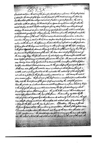
of movable cast iron. The nut is of the form of a short frustum of a cone the length of which is about 1/3. The diameter of its base and the diameter of the small end may be about 1/4 less than that of the base of the large end which I esteem a good proportion. This nut is cast solid with an opening at the centre for a square wrought iron shaft. On the conical surface are cast shallow rectangular furrows, six of which run straight across dividing the conical surface into as many equal parts and the intermediate spaces are divided equally into oblique furrows which run from the straight furrows to the front circumference of the nut. The front end is divided and furrowed in a similar manner. The case is cast with its inner surface similarly furrowed and nearly concentric with the nut. The difference in the diameter being a fraction in the proportion 1/6 being open at the large end and leaving an oblong opening at the top, contiguous to the front edge which descends obliquely to the centre of the nut laying bare the upper semicircle of the front end of the nut. The lower semicircle of the front end of the case only being therefore furrowed, by which opening the corn is fed into the nut from a hopper of ordinary construction placed over the mill. The case is also cast with ears having screw holes by which it is screwed to the inner face of the crop piece hitherto mentioned, behind and as near to the gear shaft as the gearing will permit. At the rear side of the quill a centre screw is introduced which passes through a suitable nut and being pointed at the end enters the extremity of the shaft of the nut which is fitted for the purpose and being screwed in or out causes the mill to grind coarser or finer. The front end of the shaft receives a small bevel pinion wheel which takes into the bevel pinion of the gear shaft and revolves the nut of the grinder. Below the grinder an inclined screw or riddle is placed in a frame which is hung to the crop quill already mentioned and covers the top of a discharging shoot formed by an apron that runs from the quill to the rear of the machine and and a case placed between the legs of the frame, the screw being agitated by the rattle shaft beneath it geared by a whirl band on its extremity to the whirl on the cylinder shaft already mentioned. The meal falls into a shoot where it is retained by a slide at the foot and the husks pass over.
Operation. The corn is fed into the feeder by hand whilst the machine is in revolution. The teeth of the cylinder cause it to revolve and pass down the channel and being at the same time operated on by the compression, the granated edge completely disengages the corn which falls into the shoot whilst the cob slides out at the opening in the side of the case.
Page 5.
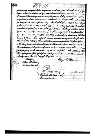
grinder may or may not be put in operation at the same time that the shelling is going on. When it is designed only to chop the corn the screen or side is removed. I have omitted giving dimensions of the parts in the foregoing description as these may be varied to suit circumstances. I shall however here give those which I prefer and find to answer practically - Length of the frame 2 feet 8 in. Height of 20 2 ft 8 in. width in clear 9 1/4 in. diameter of cylinder 13 in. length and breadth of teeth 1/2 inch. thickness of 20 1/4 in. thickness of plates about 3/8 in. diameter of spur wheel 3 in. - do of large cog wheel 16 in. feed wheel 4 in square. large diameter of the nut of the grinder 2 1/2 in diameter of the bevel pinions 2 1/2 in. Now what I claim as new and as my invention for which I ask Letters Patent is the construction and arrangement of the feeder operating with the cylinder on the principle and in the manner herein described and also the construction of the grinder by which it is enabled to grind on the conical and front surfaces at the same time, as herein set forth. I do testify that the foregoing is a true specification of my said improvement I have hereunto set my hand this 25th day of May 1835.
George W. Meador
Witnesse
Sam Attining
Isaac Hubber
(Drawing)
(Patented 12 June 1835)
Drawing made
Published accounts: journal notice
Notice in the monthly list of patents
Journal of the Franklin Institute, new ser., vol. 16 (1835), p. 143 · View the page
336. Shelling and grinding corn.-G. M. Weaver, Montgomery Square, Pa.
Published accounts: journal notice
Notice in the monthly list of patents, with remarks
Journal of the Franklin Institute, new ser., vol. 17 (1836), p. 46 · View the page
26. For a Machine for Shelling and Grinding Corn; George M. Weaver, Montgomery Square, Montgomery county, Pennsylvania, June 12.
Remarks. The shelling is effected by means of a revolving cylinder, the corn being fed in by hand; the feeder, which reacts against the cylinder, has some peculiarities in its construction, but the whole machine does not essentially differ from some others. The grinder is merely a cast iron frustrum of a cone, furrowed on its smaller end, and on its edges, which revolves in a corresponding cast iron pan or box. The claim is to "the construction and arrangement of the feeder, operating with the cylinder, in the manner described; and also the construction of the grinder, by which it is made to grind on the conical and front surfaces at the same time."
About this record
- Patentee
- DATAMP
- Date
- DATAMP
- Invention
- DATAMP
- Listed in
- the Name and Date index of patents, DATAMP, USPTO records, Jim Shaw's X-patent list, the Journal of the Franklin Institute, Burke's List of Patents (1847)
- The sources give different dates; the date shown is the one most of them agree on.
- The Franklin Institute's journal spells the name differently.
- The Franklin Institute's journal confirms the date shown.
- Burke's 1847 Patent Office list gives the same patent.
- Burke's 1847 Patent Office list gives a slightly different date; the date shown follows the standard lists.
Shaw: lists Otis, C. here as 8893½