

Drawings and documents
National Archives restored drawings: drawing
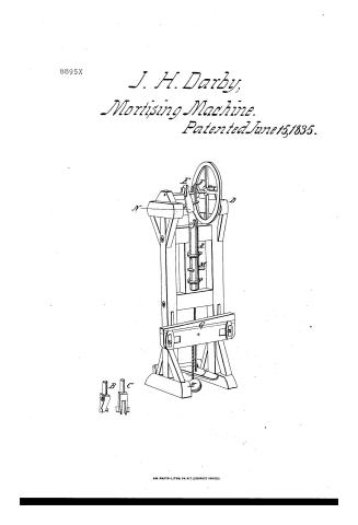
J.H. Darby's Patent Drawing for a Morticing Machine

National Archives, Restored Patent Drawings (Record Group 241) · Full-size scan at the National Archives · Catalog record
Show the text on the drawing Hide (92 words)
Words on the drawing as machine-read by the National Archives; not checked. Useful mainly for searching.
144. WOOD WORKING MACHINES. / Mortising, Chisel Cutters. / $1- / J.H. DARBY'S / MORTISING MACHINE / CLASSIFICATION / 8895-X / Patented 15 June 1835 / DIVISION. / References. / A.Spindle. / B. Morticing Chasel / C Tenoning do, - - / D.Ballance Wheel. / E. Spindle Crank.- / F. Treadle Crank. / G. Wedge. / H. Weight to move G. / I.Ireadle. / M. Handleto turn spindle / N. Swivel. / Patent Office Cepril 24" 1838- / Made under direction of the commitioner of / Matents. in conformity with the Gety 3:11 / ML ellhorth / Commissioner gePate
USPTO scan
The patent as scanned by the USPTO
-
 Page 1
-
 Page 2
-
 Page 3


U.S. Patent and Trademark Office · Google Patents
Show the transcription Hide (442 words)
Machine transcription (LightOnOCR) of the pages as scanned by the USPTO, most of them the handwritten copies made when the records were restored after the 1836 fire. Not checked; it can misread handwriting, so compare it with the scan.
Page 1.
8895X
J. H. Darby,
Mortising Machine.
Patented June 15, 1835.

A.M. PHOTO-LITHO. CO. N.Y. (OSBORNE'S PROCESS)
Page 2.
88957
June 15, 1835
Joseph H. Darty of Leominster, Massachusetts.
Letters Patent
To all to whom these presents shall come,
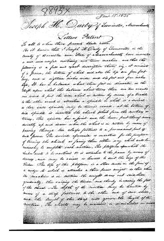
Be it known that Joseph H. Darty of Leominster in the county of Worcester and State of Massachusetts have invented a new and useful mortising and tenon machine and that the following is a full and exact description thereof viz. it consists of a frame, the bottom of which and also the top are four feet long, and is eighteen inches wide and six feet and four inches high. It has a balance wheel three feet in diameter, in the shaft upon which the balance wheel turns there are two cranks one used to put the said wheel in motion by means of a treadle to the other crank is attached a spindle in which is a screw so that said spindle may be turned round, at the bottom of said spindle is inserted the chisel which form the mortises or tenons. This spindle has a joint and the lower part thereof moves up and down when the wheel is in motion by means of passing through two clasps fastened to a permanent part of said frame. The screw aforesaid is inserted for the purpose of turning the chisel or facing them either way which will be necessary to complete each mortise. The platform upon which the timber is to be mortised is attached to the frame by means of screws, and may be raised or lowered to suit the size of the timber. The top of this platform is a slide made in the form of a wedge to which is attached a three pound weight so that when the machine is in motion the weight draws out said slide gradually, thus raising the timber and thereby increasing the feed of the chisel. The depth of the mortise may be limited by means of a strap fastened to the other end of said slide, and the length of this strap will govern the length of the mortise. The chisel may be increased or diminished in width
Page 3.
8895 X
by means of descending on or off upon the side additional wheels
a model of the above described machine is herewith submitted
April 21st 1835,
Witnesses
Gilbert Desby
Math Wood
Joseph H. Darby
(Drawing)
(408 words)
(Patented June 15, 1835)
Published accounts: journal notice
Notice in the monthly list of patents
Journal of the Franklin Institute, new ser., vol. 16 (1835), p. 143 · View the page
346. Mortising and tenoning.-Joseph H. Darby, Leominster, Mass.
Published accounts: journal notice
Notice in the monthly list of patents, with remarks
Journal of the Franklin Institute, new ser., vol. 17 (1836), p. 49 · View the page
36. For a Mortising and Tenoning Machine; Joseph H. Darby, Leominster, Worcester county, Massachusetts, June 15.
Remarks. A very brief description is given of this machine, which is so similar to others that the inventor ought certainly to have pointed out its novelties; he, however, has failed to do this, and we have failed in the attempt to discover them; there is no claim to any part of the affair. A vertical shaft, capable of swivelling, when required, receives at its lower end, the chisel by which the mortises, or tenons, are to be made. A crank shaft, carrying a fly wheel, is to move the shaft up and down, and is itself made to revolve by means of a second crank, and a treadle. The stuff to be operated upon is placed upon a regulating shifting bed. The drawing shows two forms of chisels, but we do not hear any thing about them in the specification.
DATAMP: illustration
Illustrations from DATAMP


DATAMP (Directory of American Tool and Machinery Patents), via the Internet Archive · Archived DATAMP page
About this record
- Patentee
- the Journal of the Franklin Institute, Journal
- Date
- the Name and Date index of patents, DATAMP, USPTO records
- Invention
- DATAMP
- Listed in
- the Name and Date index of patents, DATAMP, USPTO records, Jim Shaw's X-patent list, the Journal of the Franklin Institute, Burke's List of Patents (1847)
- The sources give the patentee's name differently; the name shown follows DATAMP and Shaw.
- The patentee's full name comes from the Franklin Institute's journal.
- Burke's 1847 Patent Office list gives the same patent.