

Drawings and documents
National Archives restored drawings: drawing
Reuben Daniel's Patent Drawing for a Napping Machine

National Archives, Restored Patent Drawings (Record Group 241) · Full-size scan at the National Archives · Catalog record
Show the text on the drawing Hide (38 words)
Words on the drawing as machine-read by the National Archives; not checked. Useful mainly for searching.
$220 / THIS / 28. CLOTH. / REUBEN DANIEL'S / [37] Napping. / Napping Machine / Patented June 26th 1835 / 8928-4 / lis / No: I / of / lis. / No: II. / 1500 / Fig: No. III
USPTO scan
The patent as scanned by the USPTO
-
 Page 1
-
 Page 2
-
 Page 3
-
 Page 4
-
 Page 5
-
 Page 6


U.S. Patent and Trademark Office · Google Patents
Show the transcription Hide (1,725 words)
Machine transcription (LightOnOCR) of the pages as scanned by the USPTO, most of them the handwritten copies made when the records were restored after the 1836 fire. Not checked; it can misread handwriting, so compare it with the scan.
Page 1.
8928X
R. DANIEL.
NAPPING MACHINE.
Patented June 26, 1835.
Fig. 1.
Fig. 2.
Fig. 3.
Page 2.
June 26, 1835
Reuben Daniels
Letters Patent
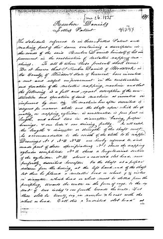
The Schedule referred to in these Letters Patent and making part of the same containing a description in the words of the said Reuben Daniels himself of his improvement in the construction of Metallic napping machines. To all to whom these presents shall come:
Be it known that I Reuben Daniels of Woodstock in the County of Windsor State of Vermont, have invented a new and useful improvement in the construction and operation of the Metallic napping machine and that the following is a full and exact description of the construction and operation of said machine as invented or improved by me. viz. The machine hereafter described is designed for narrow cloths and the shaft upon which the operating or napping cylinder is constructed is four feet in length, and about two in diameter, having proper bearings, & one loose & one driving pulley. In all cases, the length & diameter or strength of the shaft must be accommodated to the width of the cloths to be napped.
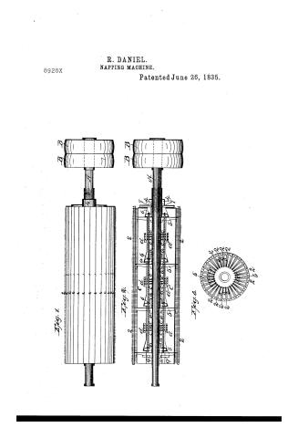
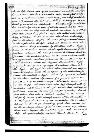
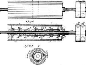
Drawings No. I No. II No. III are hereby referred to, and made part of these specifications. No. I shows the napping cylinder completed. No. II. shows a longitudinal section of the cylinder. No. III shows a radiated slot head, more perfectly described hereafter. On the shaft at a proper distance from the bearing, at the left hand end of the shaft let there be placed a metallic head or wheel of ¾ inches in diameter, which head or wheel must be slotted from the periphery, towards the centre in the form of rays, to the extent of two inches & one fourth towards the centre. Let these slots be twenty, six in number & be cast with the wheel or head. Call this a "radiated slot head" as in
Page 3.
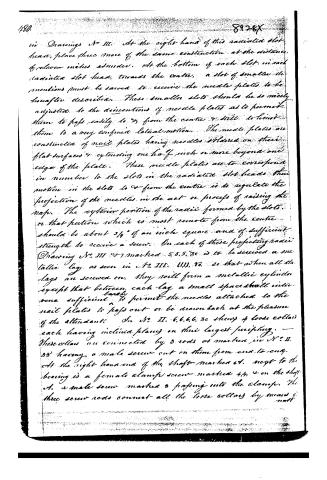
in Drawings No III. At the right hand of this radiated slot head, place three more of the same construction at the distance of eleven inches asunder. At the bottom of each slot in each radiated slot head, towards the centre, a slot of smaller dimensions must be sawed to receive the needle plates to be hereafter described. These smaller slots should be so nicely adjusted to the dimensions of needle plates as to permit them to pass easily to & from the centre & still to limit them to a very confined lateral motion. The needle plates are constructed of nail plates having needles soldered on their flat surfaces & extending one half inch or more beyond one edge of the plate. These needle plates are to correspond in number to the slots in the radiated slot heads their motion in the slots to & from the centre is to regulate the projection of the needles in the act or process of raising the map. The exterior portion of the radii formed by the slots, or that portion which is most remote from the centre should be about 3/4" of an inch square and of sufficient strength to receive a screw. On each of these projecting radii Drawing No III & marked 5, 5, 5, &c is to be screwed a metallic lag, as seen in Fig III. 4, 4, 4, &c so that when all the lags are screwed on, they will form a metallic cylinder except that between each lag a small space shall intervene sufficiently to permit the needles attached to the nail plates to pass out or be drawn back at the pleasure of the attendant. In Fig II. 6, 6, 6, 6, &c show 4 loose collars each having inclined planes on their largest periphery. These collars are connected by 3 rods as marked in Fig II. 8, 8 having a male screw cut on them from end to end. At the right hand end of the shaft marked 4, next to the bearing is a female clamp screw marked 4, 4, & on the shaft 4, a male screw marked 3 passing into the clamp. The three screw rods connect all the loose collars by means of a nut.
Page 4.
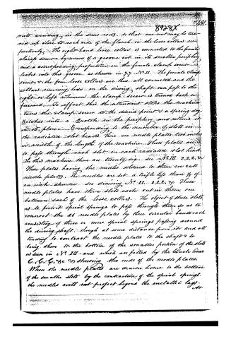
parts running in the screw rods, so that one nut may be turned up close to each side of the flanch in the loose collars respectively. The right-hand loose collar is connected to the female clamp screw by means of a groove cut in its smaller periphery and a corresponding projection in the female clamp screw locks into this groove, as shown in Fig. 11. The female clamp screw and the four loose collars are thus all connected and the collars running loose on the driving shaft can pass to the right or left whenever the clamp screw is turned back or forward. To effect this the attendant stops the machine, turns the clamp screw to the desired point and a spring dog latches into a knuckle in the periphery and retains it in its place. Corresponding to the number of slots in the radiated slot heads there are needle plates two inches in width of the length of the machine. These plates are to pass through each slot in each radiated slot head. In this machine there are twenty-six, see Fig. 11, 2, 2, 2, &c. These plates having the needles soldered to them are called needle plates. The needles are set a trifle less than 1/8 of an inch asunder, see drawing Fig. 11, 2, 2, 2, &c. These needle plates have three slots each cut in them, one between each of the loose collars. The object of these slots is to permit spiral springs to pass through them so as to connect the 26 needle plates by three circular bands each consisting of three or more spiral springs passing around the driving shaft, though at some distance from it, and all tending to contract the needle plates to the shaft and to bring them to the bottom of the smaller portion of the slots as seen in Fig. 11, and which are filled by the black lines C, C, C, &c, &c, showing the ends of the needle plates. When the needle plates are drawn home to the bottom of the smaller slots by the contraction of the spiral springs, the needles will not project beyond the metallic lugs.
Page 5.
At the left hand end of the machine around the hub of the radiated slot head & attached to & made fast to the hub is a cast iron collar extending one & half inches beyond 3 around the hub marked g drawing 18. II & the fourth of an inch in thickness. Corresponding to this collar, at the left hand end of all the needle plates, there is cut a slot one half inch in depth, as shown in g. II. All these plates being fitted onto this collar & the collar being attached to the radiated slot head, & this being fast to the driving shaft, the needle plates cannot move to the right or to the left, while at the same time the loose collars being connected by the three rods or long screws to the clamp screws at the right hand end of the machine, whenever the clamp screw is turned back or forward, the inclined plane on the loose collars will cut against the inclined plane on the needle plates & either protrude them out beyond the metallic lags or permit the spiral springs to contract them below the lags. The cylinder rolls then present an uniform smooth surface with the exception of the interstices between the metallic lags. The clamp screw is attached to the loose collars by means of a groove cut in the small end of the collar next the clamp screw as shown in II 7.7. The screw rods thus pass through all the radiated slots heads & through all the loose collars, and all turn around the driving shaft together; but the loose collars have also a lateral motion on the driving shaft by means of the clamp screw. When the motion is to the right hand end of the machine, the inclined planes on the large periphery of the loose collars cut on the inclined planes of the needle plates, & protrude them out beyond the metallic lags. When moved to the left, the spiral springs contract towards the center.
Page 6.
this operation the clamp screw and the inclined planes on the one part & the spiral springs on the other, act as antagonists mechanical powers. In this way the precise amount of projection of the needles may be graduated and secured for the various kinds & stages of the work required.
It is not material that the work of the machine be done precisely as here described, but many variations & much latitude of construction may be admitted & still the result be secured. Instead of needles, steel or other wire may be used, or the plates may be made of steel, & in place of needles, teeth corresponding to them may be cut in the plates. The remaining portion of the machine may be very similar to the teagling machine now in use, with some obvious alterations. The machine will be used much as those at present employed with the exception that the motion of the metallic napping machine is much slower than that of a teagling machine. What I claim & all I claim as my invention in this machine, is the principle or improvement of varying, gauging, or graduating the projection of the needles, wires or teeth which are designed to do the work performed by teagles in the common teagling machine. Or what will come to the same result, I claim the right of constructing the machine in such a manner as to regulate the projecting of the needles beyond the metallic lags, by moving the needle plates to or from the centre, or by so constructing it that the needle plates shall be stationary & the metallic lags be capable of being moved to & from the centre & thus wholly to conceal the needles, or to graduate their projection at the pleasure of the attendant. Woodstock, Ct. April 23d 1835
Witnesses David Price Robert Daniels David S. Powers
1782 w25
(Drawing)
Published accounts: journal notice
Notice in the monthly list of patents
Journal of the Franklin Institute, new ser., vol. 16 (1835), p. 143 · View the page
377. Napping machine. Reuben Daniels, Woodstock, Vt.
Published accounts: journal notice
Notice in the monthly list of patents, with remarks
Journal of the Franklin Institute, new ser., vol. 17 (1836), p. 56 · View the page
67. For a Napping Machine; Reuben Daniels, Woodstock, Windsor county, Vermont, June 26.
Remarks. This machine is intended for the narrow kinds of cloth. The napping cylinder is made about nine inches and a quarter in diameter, and about three feet in length. The surface consists of twenty-six lags, or strips, allowing a space between each for needles to pass in and out. The napping cylinder is hollow, and has a cylindrical shaft through its centre, upon which is fitted the necessary apparatus for projecting or retracting the needle points. This apparatus is governed by screws at the end of the cylinders. The needles are fixed on metallic plates very near together, so as to stand like the teeth of a comb. This cylinder may be so placed as to operate like the ordinary teazling machine, but its motion must be much slower. What is claimed "is the principle, or improvement of varying, gauging, or graduating, the projection of the needles, wires or teeth, which are designed to do the work, performed by teazles in the common teazling machine."
DATAMP: illustration
Illustrations from DATAMP

DATAMP (Directory of American Tool and Machinery Patents), via the Internet Archive · Archived DATAMP page
About this record
- Patentee
- DATAMP
- Date
- the Name and Date index of patents, DATAMP, USPTO records
- Invention
- DATAMP
- Listed in
- the Name and Date index of patents, DATAMP, USPTO records, Jim Shaw's X-patent list, the Journal of the Franklin Institute, Burke's List of Patents (1847)
- Burke's 1847 Patent Office list gives the same patent.