

Drawings and documents
National Archives restored drawings: drawing
William Wadsworth's Patent Drawing for a Brick Press

National Archives, Restored Patent Drawings (Record Group 241) · Full-size scan at the National Archives · Catalog record
Show the text on the drawing Hide (175 words)
Words on the drawing as machine-read by the National Archives; not checked. Useful mainly for searching.
2' / CI / DIV. 15 / carbon / Pottery, / 12. / bines, / Movable, / Reciprocaung on Piunger. / WN. WADSWORTH / CLASSIFICATION / 8.940-X / BRICK PRESS. / Palented 26" June 1835. / DIVISION. / un / REFERENCE. / A. Prame of wood / B. Bed piece / C. Plate that supports the follower and mould. / D. End prece that supports the horizontal joint. / E. / plates k.7 m / F. Uprights. / G. Guide lo the Tever. / H. Lever / I. Perpendicular tobale so joints. / J Horizonlal allo / K. Follower. / T. Filevations for Follower. / N. Mould / a. Centre eross piece 20 the frame of wood, b. Prace 2o the lowver guide. / c. slot in the puide, d, Enlargementor the upper joint. / e posts. / Weight Birdle to the to balance Mould. the Sever, h, Brace f Braces to the to Mould upright / g 2. The Dog. The beam which / to / l The plate which 25 forms attached ore to sicle plate & of the brick. / 772 / plate secureil lo ends E. / Pails o, Poller between the upright posts / Olevation for slides 077 the mould / 7* / Fastenings over the follower.
USPTO scan
The patent as scanned by the USPTO
-
 Page 1
-
 Page 2
-
 Page 3
-
 Page 4
-
 Page 5
-
 Page 6
-
 Page 7


U.S. Patent and Trademark Office · Google Patents
Show the transcription Hide (2,478 words)
Machine transcription (LightOnOCR) of the pages as scanned by the USPTO, most of them the handwritten copies made when the records were restored after the 1836 fire. Not checked; it can misread handwriting, so compare it with the scan.
Page 1.
BEST AVAILABLE COPY
NO PRINTED SPECIFICATION AVAILABLE
W. Wadsworth,
Brick Machine.
Patented June 26, 1835.
8,940x.

Page 2.
June 26, 1835
8940x William Wadsworth
Letters Patent
The Solemnly refines to in this Letters Patent and making part of the same containing a description in the words of the said William Wadsworth himself, of his improvement in a machine for manufacturing pressed bricks called the Improved Brick Press.
To all people to whom these presents shall come, William Wadsworth of Hartford in the County of Hartford and State of Connecticut, salutary greeting. Be it known that I the said William Wadsworth have invented, made, and constructed and applied to use a new and useful improvement in a machine for manufacturing pressed brick which I call the Improved Brick press, by which said brick can be made in a more perfect and rapid manner than in any mode hitherto known and used. My improvement consists in a combination of machinery, all the separate parts of which may have been heretofore known or used separately, or for other purposes, and the new combination for a new purpose, to effect an improvement in a valuable art, constitutes my invention for which I pray that the exclusive use may be secured to me according to the provisions of law. Herewith is forwarded to the Patent Office a Model and two sets of drawings by reference to which this specification can readily be understood. My machine is represented by the model and drawings as on four wheels, and it will be generally convenient to have it on wheels of convenient height, that it may be moved over the brick yard, that the bricks may be pressed by the spot where it is intended to deposit them. I make a substantial frame of iron, wood, cast iron or other material about five feet in length, and about twenty inches in width with strong posts at the corners & cross pieces, the front part being solid to meet the fixtures on the axle tree about eighteen inches high from the bottom of the wheels. This frame must be sufficiently strong, and well fastened to support the machine, and the strain on the operation. The tops of the posts are raised about two & a half inches above the
Page 3.
8940X
side pieces and ends of the frame. The sides and ends of the frame are marked a A, A, A, A, across the side frame timbers under the upright posts for sustaining the beam. E is a strong oak piece of timber or other material fastened to the side pieces of the frame by tenons or in any other convenient mode, to strengthen and sustain the beam under the upright posts. The end is seen in the drawing & marked a. The frame must be made perfectly smooth on the top except the corners. B, B, are two pieces of cast iron or other suitable metal, which I call the bed pieces. They may be about two or three inches deep & about two inches wide or any other dimensions that on experience may be found preferable. They are about five inches apart and extend the whole length of the frame to which they must be well secured; they are raised about three quarters of an inch above the frame, except that part where the plate C is let into them. They must form a smooth surface with the plate C. The ends of the bed pieces must be stout and strong, and rise about five and a half inches. The ends D are perforated with one & a half inch holes to receive the guides on the stationary end of the horizontal toggle joint; the ends E rise about the same height. These ends and bed pieces must be large and strong enough to bear their whole strain in pressing the brick without trembling. C is a plate of cast iron or other material, seventeen inches long and nine inches wide, three quarters of an inch deep and let into the bed pieces to form an even surface with them. This lies across the frame and bed pieces to which it is securely fastened. This plate has wings extending from the outer edge of the front side of it, five inches wide and two inches long coming to the front end of the frame. These wings lie on the outside of the bed pieces adjoining them, and of even height with them. The use of this is to support the elevations L, S, & P. P. likewise operate as a brace and supports to the bed pieces. H is an upright sustaining post of cast iron or other suitable material rising from one of the bed pieces about three feet six inches high, on the similar part rises from the other bed piece. The edge of which is only visible in the drawing, these must be connected by an iron bar at the top just below which are circular enlargements of the posts through which
Page 4.
8940X
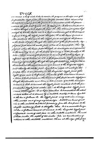
are one and a half inch holes to receive the quagons on the upper end of the perpendicular toggle joint. G is an upright wooden part at one end of the machine rising from the frame and connected with the former named upright posts by rods t.t. to steady it. In this wooden part is a slot a through which passes the lever H. This slot must extend high enough to let the lever rise to a level and low enough to let it descend so far as to bring the toggle joints straight. H is the lever of wood or other material that works the toggle joints and affects the pressure on the bricks it passes through the upper part of the perpendicular toggle joint just above its centre joint where it is secured fast. This toggle joint where the lever passes through it is enlarged as is represented on the drawing a. a. for the purpose of securing a better purchase to the lever. I is a weight fastened to one end of the working lever of sufficient size to balance it. I I is the perpendicular toggle joint which turns on quagons passing through the upright sustaining posts joined in the middle in the usual manner and secured to the horizontal toggle joint close by its center joint by a bolt on which it works for this purpose. There is an elevation in the horizontal toggle joint of the height of one and a half inches. The center of this is cut down to receive a tenon which is made on the lower end of the perpendicular toggle joint through the elevation and tenon a hole is made of suitable dimensions to receive a bolt to connect the toggle joint on which bolt the perpendicular toggle joint works. J J is the horizontal toggle joint secured stationary at D as before described but moveable at the attachment a end where it is secured by a suitable matize & tenon by a bolt to the bar or follower K. The toggle joints are of cast iron or any other metal and of any required size. P.P.P.P. are braces of cast iron or other suitable material proceeding from the bed pieces to the upright sustaining posts to strengthen them. It is a moveable horizontal bar or follower secured at one end to the horizontal toggle joint as before said made of cast iron or other suitable material. The width of these is 4 inches, the depth of two inches. L.L.L. are two elevations of cast iron or other suitable material. The one at the edge of the plate C.
Page 5.
8940X
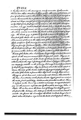
C. the other which in the drawing is nearly concealed by the mould. There are two others similar to them on the other side of the plate, all four of which are cast on the plate C. They are raised high enough to receive the movable bar or follower K, through which it passes in spaces cut large enough for it to move freely in, secured in those places by strips of iron passing over by screws on the tops of the elevations marked e, e, g, g, which I call the bridge. I have called the base. These are made of wrought iron, one to move forward and back the mould M, which receives and holds the brick while in the process of pressing. The bridge, g, g, is fastened by bolts or screws to the outside of the lower parts of the mould M, on each side of it, and the base, h, is in the like manner fastened to the upper side of the mould. These are in a shape as appears by the drawing, and model to the requisite height where they are firmly fastened together. There the base stops and thence the bridge pieces change their direction and proceed back horizontally over a roller between the upright sustaining posts marked O.
The sides of the bridge where it proceeds horizontally are about two inches apart at the commencement of the horizontal part. They are secured by a permanent bolt-back of which are two cast-steel rollers on which the cog i is fastened to the beam I plays. These rollers are scarcely visible on the drawing, but may be readily understood by the following description. They are placed about two inches apart between the sides of the bridge supported by gudgeons passing through the sides of the bridge so formed that they will readily turn round. The cog a, at its lower and ordinarily act between these two rollers. The beam I is attached to the perpendicular toggle joint one inch above the centre joint, extending twelve inches parallel with it. The cog i is fixed on the beam by a socket and wedge to adjust it that plates are in the manner represented by the model & drawing. When the lever H is born down the lower end of the cog i is brought against the front roller between the sides of the bridge and carries it with the mould M forward till it encloses the block V which brings it to the point where the pressure is given to the bricks at which point the lever
Page 6.
8940X
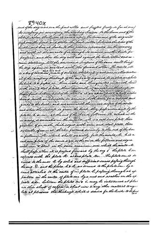
end of the dog rises over the front roller and fuses freely—so far as may be necessary for conveying the working lever to the lower end of the slot. C. When the lever is raised up, the lower end of the dog will pass over the front and strike the back roller between the sides of the buckle and bear it back to the position represented in the drawing and with it the mouth for enough to receive another brick for pressure and then the dog will act against the back roller and remain stationary till the downward pressure of the same will bring the dog again in contact with the front roller. The mouth M. is a box of two sides made of suitable thickness of cast iron or other material of the necessary thickness of the capacity required to make and hold the brick to be fused in. Three inches and three quarters in width lined with iron & steel plates three sixteenths of an inch in thickness. On the front bottom part of the mouth is an apron two & a half inches broad with an elevation on one end both serve for a support and guide to the brick, and are even with the inner surface of the mouth and when the impulse is given the brick they pass under and by the plates h. a. m. at the end of the bar or follower H. which in the drawing is concealed in the mouth. M. is a cast iron plate three quarters of an inch thick edged with iron and steel plates three sixteenths of an inch thick fastened securely to the end of the bar or follower H. which shall exactly fill the mouth M. h. is a cast iron plate of the same size as the one on the follower and edged with iron & steel in the same manner over which the mouth M. shall pass when it is pressed forward by the dog i. The plate L. corresponds with the plate H. as does plate M. The plate M. is secured to the ends C. by bolts and sufficient screws passing through the ends C. and the plates h. & h. are secured to the plate M. by a screw attached to the centre of a plate L. passing through an aperture in the centre of plate M. by a nut and washer on the opposite side. Between the plates M. & C. may be introduced at pleasure thin sheets of copper or sheet iron or any other material to regulate at pleasure the thickness which is desired for the brick to be fused.
Page 7.
44. 8940X
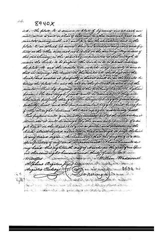
Sec. 1. The plate 10 is secured to plate 6, by means one at each end, and is a cast or slab of cast iron or other material, cast on the moulds moving with it, and to provide the elevations cut on the plate 6, on which it moves. There are eyes for any rails and fixtures on the other side not exhibited on the drawing. My means of this machinery, on the drawing represented as that enough to receive the brick to be pressed. The brick is to be placed between the plate 10 and the mould 11, which may readily be made so that on moving the lever 16 the mould 11 shall press on the brick and anode it perfectly so that it shall be in the mould between the plate 10 and the one on the following mould on the mould. Then by pressing down the working lever 16 by hand power, the two toggle joints will be raised until they are both made perfectly straight. The horizontal toggle joint being perfectly level and the perpendicular toggle joint being perfectly straight between the two upright sustaining parts. This pressure will gradually increase, and at the point where it terminates it will be enough by the manually pressure of a single hand on the lever 16 to give a power and pressure on the brick almost beyond calculation, and enough to press the brick to any desired degree. On testifying that the foregoing is a true specification of my said improvement, I have hereunto set my hand this eighteenth day of March in the year four thousand one thousand eight hundred and thirty-five.
Witnesses
Alphons Bigelov
Augustus Peabody
William Wadsworth
2632 md
(Drawing)
Published accounts: journal notice
Notice in the monthly list of patents
Journal of the Franklin Institute, new ser., vol. 16 (1835), p. 143 · View the page
370. Pressing brick.-William Wadsworth, Hartford, Conn.
Published accounts: journal notice
Notice in the monthly list of patents, with remarks
Journal of the Franklin Institute, new ser., vol. 17 (1836), p. 54 · View the page
60. For a machine for Pressing Brick; Wm. Wadsworth, Hartford, Connecticut, June 20.
Remarks. This improvement is said to consist in a combination of machinery to effect a new purpose; the respective parts of which machinery may all have been individually used for the same or other purposes. It is a toggle joint press, bearing a very considerable resemblance to other toggle joint presses, which have been employed for the same purpose. We do not think that its new arrangements are so characteristic as to "distinguish it from all other things before known or used," without some specific pointing out of its novelties.
About this record
- Patentee
- DATAMP
- Date
- the Name and Date index of patents, DATAMP, USPTO records
- Invention
- DATAMP
- Listed in
- the Name and Date index of patents, DATAMP, USPTO records, Jim Shaw's X-patent list, the Journal of the Franklin Institute, Burke's List of Patents (1847)
- The Franklin Institute's journal spells the name differently.
- The Franklin Institute's journal gives a different date.
- Burke's 1847 Patent Office list gives the same patent.