

Drawings and documents
National Archives restored drawings: drawing
Albert Bingham's Patent Drawing for a Door Latch and Lock

National Archives, Restored Patent Drawings (Record Group 241) · Full-size scan at the National Archives · Catalog record
Show the text on the drawing Hide (55 words)
Words on the drawing as machine-read by the National Archives; not checked. Useful mainly for searching.
#1 70; LOOKS & LATOHES, / Patented. July 7.1835 / V Latohes & Looks ILBERT BINC / Page 33: / Combined. / Door Latch and Lock / 89497 / Palented July 1.th 1835, / DIVISION. / 1. / Frig 2. / II / Frig's / Frig / A- bolt lateh / B- out / D the guard balt / A'-lock bolt / Fro 4.
USPTO scan
The patent as scanned by the USPTO
-
 Page 1
-
 Page 2
-
 Page 3
-
 Page 4


U.S. Patent and Trademark Office · Google Patents
Show the transcription Hide (1,190 words)
Machine transcription (LightOnOCR) of the pages as scanned by the USPTO, most of them the handwritten copies made when the records were restored after the 1836 fire. Not checked; it can misread handwriting, so compare it with the scan.
Page 1.
8949X
No Printed Specification Available
A. Bingham,
Door Latch.
Patented July 7, 1835.
Fig 1
Fig 2
Fig 3
Fig 4
Fig 5
A.M. PHOTO-LITHO. CO. N.Y. (GIBBONS'S PROCESS)
Page 2.
8949x
July 7, 1835
Albert Bingham, of Unity, Me.
Letters Patent
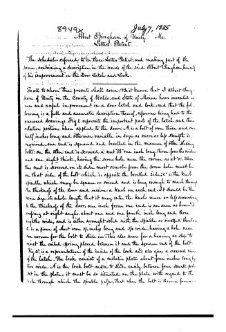
The Schedule referred to in these Letters Patent, and making part of the same, containing a description in the words of the said Albert Bingham, himself of his improvement in the Door Latch and Lock.
To all to whom these presents shall come: Be it known that I Albert Bingham of Unity in the County of Waldo, and State of Maine have invented a new and useful improvement in a door latch and lock, and that the following is a full and accurate description thereof, references being had to the annexed drawings. Fig. 1. represents the important parts of the latch and their relative positions, when applied to the door. A is a bolt of iron three and one half inches long and otherwise variable in size as more or less strength is required. One end is squared and bevelled in the manner of other sliding bolts; on the other end is screwed a nut "B" one inch long, three fourths wide and one eight thick, having the screw hole near the corner as at "a". When this nut is screwed on its side most remote from the screw hole must be on that side of the bolt which is opposite the bevelled side. "c" is the knob spindle which may be square or round and is long enough to reach through the thickness of the door and receive a knob on each end. It should be the same size its whole length that it may enter the knobs more or less according to the thickness of the door. One inch from one end is an arm or brace "D" crossing at right angles, about one and one fourth inch long and three eighths wide, and is either wrought solid with the spindle or rivetted thereto. E is a piece of sheet iron 1/2 inch long and 3/4 wide, having a hole near one corner for the bolt to slide in. This also serves for a bearing or slot to resist the coiled spring placed between it and the square end of the bolt. Fig. 2. is a representation of the inside of the lock and also gives a reversed view of the latch. The lock consists of a metallic plate about four inches long by two wide. A' is the lock bolt made to slide easily between four small posts set in the plate. It must be so situated on the plate with regard to the hole through which the spindle passes, that when the bolt is thrown forward...
Page 3.
as in the act of locking, its end shall pass immediately behind the nut B and thus prevent the latch bolt from being thrown back. About 3/4 of an inch from the end of this lock bolt is a shoulder, which meeting one of the posts prevents the lock bolt from moving too far in that direction. To the post at the other end and on the opposite side of the bolt is rivetted one end of a flat spring "c", with its other end so curved as to bear on the lock bolt and pass over a swell therein when it is moved. On the side opposite the spring is a notch "b" in which the key takes its hold when turning on the pivot "c". The bolt is confined to the plate by a small button or knob represented by figure 3, which passes through the plate and bolt and is confined by a screw and nut as at "e" fig. 2. In the plate is cut a hole for the lesser shoulder of the button or knob to slide in. D is a guard bolt attached to the plate like the lock bolt and is so situated on the plate that it may intersect the lock bolt, and prevent its being thrown back by the key, or I effect the same object by a small button on the outside of the plate, which checks the knob fig. 3. Fig. 4 shows the form of a brass knob to be used on a square spindle. The small neck is to pass through the escutcheon or lock plate and forms the arbor on which the knob and spindle turn. At "b" is a notch in the shoulder of the knob to receive the dog represented by fig. 5, which is to be attached to the inside escutcheon and made to take its hold in said notch when the work is put together, thus forming an inside fastening when the latch is used without the lock. The escutcheon and plate may be formed variously as strength or beauty is required.
The mode of applying the above door latch and lock to the door is to bore an inch and a half hole into the door stile at a convenient height—three fourths of an inch deep, forming a chamber for the nut and the arms of the spindle to move in, and being at such a distance from the edge of the door as to allow the latch bolt to project the whole length of its bowl. Then bore a hole into the edge of the door for the latch bolt and coiled spring in. If the hinges are upon the right when the operation is on the inside of the door, this last hole must be bored so much above the center of the first as to allow the latch bolt to pass just over the spindle, and if on the other hand it must be as much below. The sheet iron bearing or stop must be driven in edge-wise across the chamber perpendicularly so that
Page 4.
8949X
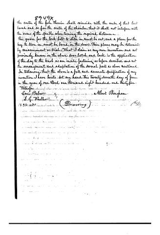
the centre of the hole therein shall coincide with the center of that last bored and so far the center of the chamber that it shall not interfere with the arms of the spindle when turning the required distance.
The groove for the lock bolt to slide in, must be cut, and a place for the key to turn in, must be bored in the door. Their places may be determined by measurement or trial. What I claim as my own invention and not previously known in the above door latch and lock is the application of the dog to the knob as an inside fastening as before described and not the arrangement and adaptation of the several parts as above mentioned.
In testimony that the above is a full and accurate specification of my invention I have hereto set my hand this twenty-seventh day of June in the year of our Lord one thousand eight hundred and thirty-five.
Witnesses:
Louis Beber
S. G. Theller
Albert Bingham
(12.3.2.1835) (Drawing)
Published accounts: journal notice
Notice in the monthly list of patents
Journal of the Franklin Institute, new ser., vol. 16 (1835), p. 215 · View the page
402. Locks and latches.-Albert Bingham, Unity, Maine,
Published accounts: journal notice
Notice in the monthly list of patents, with remarks
Journal of the Franklin Institute, new ser., vol. 17 (1836), p. 123 · View the page
14. For a Door Latch and Lock; Albert Bingham, Unity, Waldo county, Maine, July 7.
Remarks. Many variations in spring latches and knobs for doors have been patented within a very few years. The claim made by the present patentee is a very brief one, being merely "the application of the dog to the knob as an inside fastening, as described."
About this record
- Patentee
- DATAMP
- Date
- the Name and Date index of patents, DATAMP, USPTO records
- Invention
- DATAMP
- Listed in
- the Name and Date index of patents, DATAMP, USPTO records, Jim Shaw's X-patent list, the Journal of the Franklin Institute, Burke's List of Patents (1847)
- Burke's 1847 Patent Office list gives the same patent.