

Drawings and documents
National Archives restored drawings: drawing
F. Stedman's Patent Drawing for a Machine for Planing Dovetailing, etc.

National Archives, Restored Patent Drawings (Record Group 241) · Full-size scan at the National Archives · Catalog record
Show the text on the drawing Hide (41 words)
Words on the drawing as machine-read by the National Archives; not checked. Useful mainly for searching.
144. WOOD WORKING MACHINES. / [17 / Planing & Matching, / page 147 our 22 / F. S TED M / #2- / (4 / MACHINE / Sumber / (Forz / Planing Dovetailingr / DIV / Putented / oR / Frmm a detached drawing.
National Archives restored drawings: drawing
Fisher Stedman's Patent Drawing for a Machine for Matching and Dressing Boards

National Archives, Restored Patent Drawings (Record Group 241) · Full-size scan at the National Archives · Catalog record
Show the text on the drawing Hide (49 words)
Words on the drawing as machine-read by the National Archives; not checked. Useful mainly for searching.
144. WOOD-WORKING MACHINES. / S. / Planing and Matching. / matching / FISHER STEDMAN / CLASSINICATION / Patent Machine sumber / 9035-X / For / DIVISION. / Malching and Dressing board / Palented / to / Mik for matching (Docessire / Aug. 17. 1835, / boards for floors, more etc / III
USPTO scan
The patent as scanned by the USPTO
-
 Page 1
-
 Page 2
-
 Page 3
-
 Page 4
-
 Page 5
-
 Page 6


U.S. Patent and Trademark Office · Google Patents
Show the transcription Hide (2,185 words)
Machine transcription (LightOnOCR) of the pages as scanned by the USPTO, most of them the handwritten copies made when the records were restored after the 1836 fire. Not checked; it can misread handwriting, so compare it with the scan.
Page 1.
9035X
F. Stedman,
Planing and Matching Machine.
Patented Aug. 17, 1835.
NO PRINTED SPECIFICATION AVAILABLE

Page 2.
40357
Aug. 14, 1835 149.
Fisher Steedman
Letters Patent
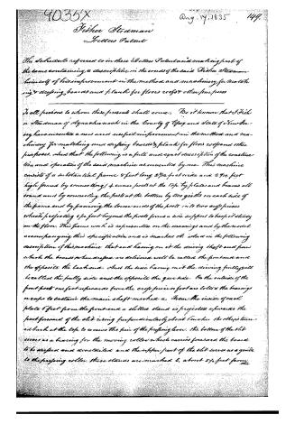
The Schedule referred to in these Letters Patent and making part of the same containing a description in the words of the said Fisher Steedman himself of his improvement in the method and machinery for matching and dressing boards and planks for floors, roofs and other purposes.
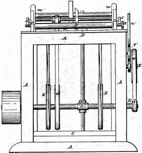
To all persons to whom these presents shall come: Be it known that I Fisher Steedman of Aquachanook in the County of Essex and State of New Jersey have invented a new and useful improvement in the method and machinery for matching and dressing boards & planks for floors, roofs and other purposes. And that the following is a full and exact description of the construction and operation of the said machine as invented by me. This machine consists of a substantial frame 8 feet long, 2 7/10 feet wide and 2 7/10 feet high formed by connecting 4 corner posts at the top by plates and beams all round and by connecting the posts at the bottom by two girders on each side of the frame and by forming the lower ends of the posts into two crook pieces which projecting 6 1/2 feet beyond the posts forms a side support to keep it steady on the floor. This frame work is represented on the drawings and by the model accompanying this specification and is marked A. And in the following description of this machine that and having on it the driving shaft and from which the boards when dressed are delivered will be called the front end and the opposite the back end. And the side having on it the driving pulley will be called the pulley side and the opposite the gear side. On the outside of the front posts one foot upwards from the crook pieces or foot are bolted the bearings or caps to sustain the main shaft marked a. From the inside of each plate 6 feet from the front end a slotted stand is projected upwards the part forward of the slit rising perpendicularly about 6 inches, the other is turned back at the top to receive the pin of the pressing lever. The bottom of the slit serves as a bearing for the moving roller which carries forward the board to be dressed and denailed and the upper part of the slit serves as a guide to the pressing roller. These stands are marked b, about 5 1/2 feet from the
Page 3.
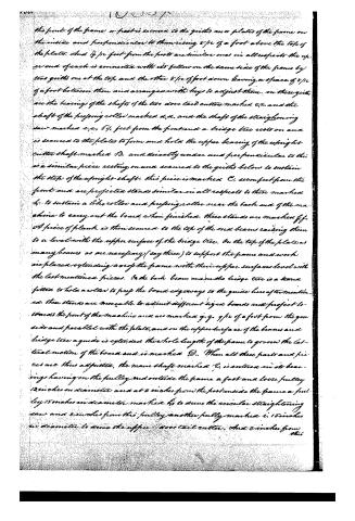
the front of the frame a post is secured to the girths and a plate of the frame on the inside and perpendicular to them rising 8/12 of a foot above the top of the plate. And 12/12 feet from the posts are similar ones in all respects the upper end of each is connected with its fellow on the same side of the frame by two girths one at the top and the other 8/12 of foot down leaving a space of 8/12 of a foot between them and arranged with keys to adjust them. In these girths are the bearings of the shafts of the two above tail cutters marked c,c, and the shaft of the profiling roller marked d,d, and the shaft of the straightening saw marked e,e, 6 1/2 feet from the front and a bridge tree rests on and is secured to the plates to form and hold the upper bearing of the upright cutter shaft marked B, and directly under and perpendicular to this is a similar piece resting on and secured to the girths below to sustain the step of the upright shaft. This piece is marked C, seven feet from the front and are projected stands similar in all respects to those marked b, to sustain a like roller and profiling roller near the back end of the machine to carry out the board when finished. These stands are marked f,f. A piece of plank is then secured to the top of the end beams raising them to a level with the upper surface of the bridge tree. On the top of the plates as many beams as are necessary (say three) to support the frame and work are placed extending a foot of the frame with their upper surfaces level with the last mentioned pieces. On the back beam and on the bridge tree is a stand fitted to hold a roller to prep the board edgesways to the guide hereafter mentioned. These stands are moveable to admit different sizes boards and project towards the front of the machine and are marked g,g, 9/12 of a foot from the near side and parallel with the plates, and on the upper surface of the beams and bridge tree a guide is extended the whole length of the frame to govern the lateral motion of the board and is marked D. When all these parts and pieces are thus adjusted, the main shaft marked E, is entered in its bearings having on the pulley end outside the frame a fast and loose pulley 12 inches in diameter and at 2 inches from the post inside the frame a pulley 15 inches in diameter marked h, to drive the circular straightening saw and 2 inches from this pulley another pulley marked i, 15 inches in diameter to drive the upper above tail cutter. And 2 inches from this
Page 4.
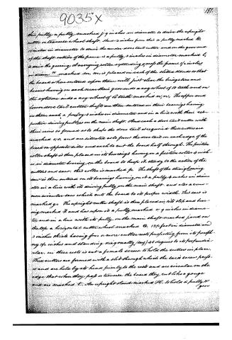
this pulley a pulley marked j 9 inches in diameter to drive the upright cutter or traverse wheel shaft. One 3 inches from this a pulley marked k, 15 inches in diameter to drive the under dove tail cutter and on the gear end of the shaft outside of the frame is a pulley, 3 inches in diameter marked l, to drive the gearing of a carrying roller extending 90° of the frame 14 inches in diameter marked m. m, is placed in each of the slitter stands so that the board when entered upon them will just clear the bridge piece and beams having on each near their gear ends a cog wheel of 18 teeth and on the extreme ends a cog wheel of 60 teeth marked n, n. The upper and lower dove tail cutter shafts are then entered in their bearings having on them each a pulley 4 inches in diameter and in a line with their respective driving pulleys on the main shaft. And each a dove tail cutter with their rims so formed as to shape the dove tail as required these cutters are marked o, o, and are situated as to form the dove tail on each edge of the board on opposite sides and each to cut the board half through. The friction roller shaft is then placed in its bearings having on a friction roller 4 inches in diameter bearing on the board to keep it steady to the action of the cutters and saw. This roller is marked p. The shaft of the straightening saw is then entered on its bearings having on it a pulley 4 inches in diameter in a line with its driving pulley on the main shaft, and also a common circular saw which cuts the board to its proper width. This saw is marked q. The upright cutter shaft is then placed in its step and bearing marked r, and has upon it a pulley marked s 9 inches in diameter and in a line with its pulley on the main shaft marked j, and on the top a horizontal cutter wheel marked t, 13 1/4 feet in diameter and 3 inches thick having four or more cutter rests projecting from its periphery 14 inches and standing diagonally (say) 45 degrees to its perpendicular. In these rests is cut a female screw to hold the cutter in place. These cutters are formed with a slit through which the said screw projects and are held by its head firmly to the rests and are circular on the edge that when they pass or traverse the board they cut like a gouge and are marked u. An upright stand marked v, to hold a pulley v gear
Page 5.
102.
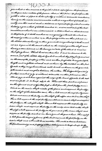
gear wheel is then secured to the girth v plate 4 feet from the front end on the gear side outside of the frame. And in this place 1 1/2 feet from the girth a stud is fixed to hold a pulley 9 inches in diameter marked w, having on the inside and connected with it a cog wheel of 18 teeth directly over this and at such a distance as to gear properly into it is a stud holding a gear wheel of 6 teeth marked v, and on each side of the last mentioned wheel is an intermediate or stud wheel on studs secured to the plates of 6 teeth marked w, and gearing also into the wheels on the moving rollers marked n, n, the pressing rollers are then placed in the slitted stands having on their gear ends a cog wheel of 18 teeth marked xx to gear into the small wheels on the moving roller shaft and having a cone turned in the bearing outside of the stand to receive the pressing levers. Which levers are marked I, and are secured to the curved part of the slitted stands by a bolt on which they play freely and rest on the cones of the pressing rollers and are then projected to any suitable length and weighted at each end as shown by the model on the pulley side or they may be continued all to roll as shown on the gear side of the model and weighted between the rollers. The horizontal guiding pulleys marked y, y, 4 inches in diameter are then placed in their stands y, y, so as to bear against the edge of the board opposite to the rest and compel it to keep steady to it. When all these parts and pieces are thus formed and adjusted pass a belt from the first pulley mentioned on the main shaft inside of the frame and around the pulley on the shaft of the circular saw, then a belt round the next pulley mentioned and around the pulley on the shaft of the upper dovetail cutter shaft. Then a belt around the next pulley mentioned on main shaft and around the pulley on the upright shaft then a belt around the next pulley on main shaft and around the pulley on the under dovetail cutter shaft, then pass a belt around the pulley on the gear end of the main shaft and around the pulley marked w, having on it the gear wheel. Then pass a belt from the moving power of the mill around the first pulley on the main shaft and all will be in motion. Then enter a board between the front moving and pressing rollers taking care to keep it up to the guide.
Page 6.
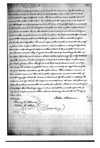
guide until it is partly entered and it will be drawn on by the motion of the rollers until it reaches the dove tail cutters when a dove tail will be cut on each edge of opposite sides. The saw will cut it to a width at each end and the cutters on the wheel C will traverse the upper side and depress it to a trough and by pressing on it will leave it perfectly depressed and smooth on the surface and it will be passed out of the machine in form of the miniature piece marked H in the model and as soon as one board is fully entered another may be put in and the machine be kept constantly at work and all the boards will match truly and form with each other perfect joints when laid together. The advantages of this machine consists when drying boards for roofs is that each dove tail will form a trough by which the water will always be passed without leak to the end of the board and for whatever purpose they may be used this mode of matching has this advantage that the joints become closer instead of opening by a slight shrinking of the board which must give a decided advantage in floors and for all purposes where the object is to keep out cold and wet, and by traversing the cutters across the board I am enabled to dry boards of the hardest timber as well as of the softer kind. What I claim as new in this improvement is the whole of the apparatus and combination of machinery by which the board is traversed by the cutters in depressing the surface and by which the edges are matched in the dove tail form as described above and is the invention for which a Patent is now prayed.
In witness that the foregoing is a true description and specification of my said improvement I have hereunto set my hand this 12th day of June 1835.
Witnesses
Henry W. Havens
Olisha J. Abel
Peter Steadman
2310 1287
E. A.
CH. JU
Published accounts: journal notice
Notice in the monthly list of patents
Journal of the Franklin Institute, new ser., vol. 16 (1835), p. 287 · View the page
488. Planing machine. Fisher Stedman, Aquackanackin, New York,
Published accounts: journal notice
Notice in the monthly list of patents, with remarks
Journal of the Franklin Institute, new ser., vol. 17 (1836), p. 206 · View the page
46. For a machine for Planing and Matching Boards; Fisher Stedman, Acquackanockin, Essex county, New Jersey, August 17.
Remarks. The specification of this patent is equally laboured and obscure, yet it is manifest that the writer has desired to make it plain. It seems as though the model had been depended upon to make the machine known, as the drawing, although on three sheets of paper, can scarcely be said to illustrate any thing. Toothed wheels, revolving cutters, saws, &c., &c., are all represented by simple lines, so that the man who should attempt to make the machine, must invent it in all its details. We learn, however, after much labour, that boards are to be planed by a round horizontal cutter wheel, under one side of which they are to be passed, by the aid of pressing rollers. The matching is to be by a dovetailed joint formed by horizontal cutters, which take away half the stuff on opposite sides towards each edge, thus, if we understand the thing correctly. The claim is to "the whole apparatus and combination of machinery by which the board is traversed by the cutters in dressing the surface, and by which the edges are matched in the dovetail form, as described above, and is the invention for which a patent is now prayed." The first part of this claim is altogether untenable, the dressing of boards by traversing cutters, in the way described, having been practised in numerous instances. Dovetail cutters were used at the navy yard in Washington, sixteen or eighteen years ago, for matching wharf timbers, and they were not then new; still, in the combination with the other machinery, had that not been altogether old, it possibly might have been sustained.
DATAMP: illustration
Illustrations from DATAMP


DATAMP (Directory of American Tool and Machinery Patents), via the Internet Archive · Archived DATAMP page
About this record
- Patentee
- DATAMP
- Date
- DATAMP, USPTO records, Burke's List of Patents (1847)
- Invention
- DATAMP
- Listed in
- the Name and Date index of patents, DATAMP, USPTO records, Jim Shaw's X-patent list, the Journal of the Franklin Institute, Burke's List of Patents (1847)
- The sources give different dates; the date shown is the one most of them agree on.
- The Franklin Institute's journal confirms the date shown.
- Burke's 1847 Patent Office list gives the same patent.