

Drawings and documents
National Archives restored drawings: drawing
Thomas Odiorne's Patent Drawing for a Rotary Pump

National Archives, Restored Patent Drawings (Record Group 241) · Full-size scan at the National Archives · Catalog record
Show the text on the drawing Hide (72 words)
Words on the drawing as machine-read by the National Archives; not checked. Useful mainly for searching.
108, PUMPS. / [118] Windinss / [94] / Sanda / for fz. / Thomas Octiorie's / Restored to the office / CLASSIFICATION / 9061.1 / 3 Buly 1sb 1853 / DIVISION. / Philis / Rolary Pump / Patented anything 1835 / 90.61 / Q. / houk by which the shipper rods arekept in place. / co / July 2 1853 / The original drawing of which thesis / a copy was de tacked from the Patent / when AS received m Intere at the Patent Office
USPTO scan
The patent as scanned by the USPTO
-
 Page 1
-
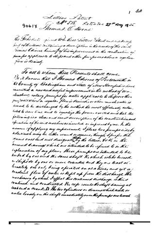 Page 2
-
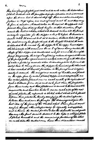 Page 3
-
 Page 4
-
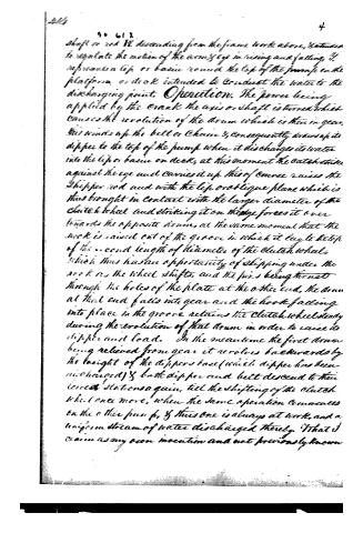 Page 5
-
 Page 6


U.S. Patent and Trademark Office · Google Patents
Show the transcription Hide (1,710 words)
Machine transcription (LightOnOCR) of the pages as scanned by the USPTO, most of them the handwritten copies made when the records were restored after the 1836 fire. Not checked; it can misread handwriting, so compare it with the scan.
Page 1.
9061X
T. Odiorne,
Windlass Water Elevator.
Patented Aug. 27, 1835.

Page 2.
Letters Patent
No 578. Dated the 27th Aug 1835
9061X Thomas Odorne
The Federal Register refers to the above Patent and in the copy
front of the document contains a description in the words of the said
Thomas Odorne himself of his improvement in the construction of
pumps applicable to ships and other purposes where a regular
flow is desired.
To all to whom these Presents shall come—
Be it known that I Thomas Odorne of Portsmouth in
the County of Rockingham and State of New Hampshire have
invented a new and useful improvement in the method of con-
structing rotary pumps for water applicable to ships or other
purposes where a regular flow is desired, or when much water is
issued to be discharged by the method the most effectively calcu-
lated to save time and to equalize the power exerted and that the
following is a clear and exact description of the construction and
operation of the said machine as invented or improved by me. In the
manner of applying my improvement, I place two pumps side by
side, which may be either round or square, though I prefer the
square ones and will designate by the letters $P_1$ & $P_2$ in the
annexed drawings which are intended to be referred to in the
explanation of my plan. These pumps are intended to be
driven by one and the same shaft $K$, which is to be turned
in ships so by one or more cranks, and they are to act al-
ternately one only being operated on at a time, and yet a
constant flow of water is kept up from the discharge. The
machinery by which I effect this continued discharge is thus
combined and constructed. $K_1$ represents the shaft having at
its end a crank, $D$. The two cylinders or drums which work or
revolve loosely on the shaft immediately over the pumps one touch
Page 3.
They have flanges projecting at each end so as to retain the belt or chain (which descends into the pump) in its proper situation so it is not moved upon the drum lest it should slip off. There are also small projections or cogs upon one end of each axis at E, and there may be four in number. A small collar on the axis at the opposite end prevents them from sliding back too far in that direction. F represents the belt or chain, which is to descend as low into the pump as may be requisite for the dipper or box G to fall. It has also a small catch H secured to it at a certain distance below the cylinder such as may be proportioned to the height to which the water is intended to be raised by the dipper G. G the upper box or dipper which is made with a narrow base I of some heavy metal. The shape of this dipper is so constructed as to fit across the bore of the pump diagonally, the wings J unfolding outwards against the sides of the pump (where square ones are used) in ascending with their load of water, folding inwards when descending so as to permit the metal base to carry down the dipper by unwinding the chain until it has reached its lowest position in the pump and is again ready to ascend. The wings are made of leather, and faced on the upper face by metal plates (copper is well adapted) K are two metal plates placed one on each end E of the cylinder at such a distance from said end as to just clear the projection from those ends, and these plates are secured to the axis so as to be immovable, and have two holes L one on each side of the axis of each plate. M, represents a clutch wheel which is to be placed between these plates K, thereby occupying the central space between them and over the pumps. The drawings will give the best idea of the form of the clutch wheel. I have found most useful, though other shapes may be equally well applied, and in his one the central portion has the diameter much greater than any other part so as to descend to the lips, or oblique plates A placed beneath it and the remaining portions of the wheel on each side the central one, have their diameters much
Page 4.
decreased, those at 2 being much less than that at 1, but when 2 1/2 the diameter is still decreased to form a groove 3. On each outer end of the parts 2, are placed two pins O, projecting outwards or towards the plate K, which they are intended to pass through by the openings or holes I, left therein for that purpose far enough to strike on or to join against the projections or cogs E, so as to work gear with them and as the axis turns, so will the cylinder turn into which the pins are geared. These pins are also just long enough to reach out of parts 2, to allow them to be driven at one end, into the holes of the plate K, and entirely through, until the parts 2 join the plate K, while those pins at the other end 2, are drawn out of the plate K so far as to leave just enough to be set on by in the plate so as still to have the clutch wheel forced round by the revolution of the plates or the connection of the pins. That part of the main axle R, upon which the clutch wheel slips back and forwards may be either round or square Q Q, represent the shipper rods for the shape of which I refer to the drawings. These are let into the sides of the center post S, next to the pumps, and there retained but in such a manner as to allow them to rise up or descend as required. The oblique plates or lips M, not and notch on the top of the center post S, are connected with the shaft of the shipper rod, which is just then confined by a small groove or catch T secured to the top of the pedestal behind the lips. Above this part the rod rises and bends over the clutch wheel at the part 2, which it encircles partly or nearly half round like a hook, of sufficient width to fall into the groove 3 when required. The upper arms projecting from the rod at right angles and extending far enough beyond the drums D, to admit of eye S underneath, for the belt or chain to run through and also to admit a round hole 6 beyond the eye through the end of the arm intended to slide up and down upon a
Page 5.
shaft or rod VV, descending from the frame works above, & intended to regulate the motion of the arm & eye in rising and falling. It represents a lip or basin mounted the top of the frame on the platform or deck intended to conduct the water to the discharging point. Operation. The power being applied by the crank the axis or shaft is turned which causes the revolution of the drum which is then in gear, this winds up the belt or chain & consequently draws up its dipper to the top of the pump when it discharges its water into the lip or basin on deck, at this moment the catch strikes against the eye and carries it up this of course raises the dipper rod and with the lip or oblique plane which is thus brought in contact with the larger diameter of the clutch wheel and striking it on the edge forces it over towards the opposite drum, at the same moment that the hook is raised out of the groove in which it lay to the top of the second length of diameter of the clutch wheel, which thus has an opportunity of slipping under the work as the wheel shifts, and the pins being thrust through the holes of the plate at the other end, the drum at that end falls into gear and the hook falling into place in the groove retains the clutch wheel steady during the revolution of that drum in order to raise its dipper and load. In the meantime the first drum being relieved from gear it revolves backwards by the weight of the dipper base (which dipper has been discharged) & both dipper and belt descend to their lowest stations again, till the shifting of the clutch wheel once more, when the same operation commences on the other pump, & thus one is always at work, and a uniform stream of water discharged thereby. What I claim as my own invention and not previously known
Page 6.
9061X
5 44
the above described machine — is not the principle raising water by means of a rotary pump, but for improvement applied to a practical use, effected a combination of various mechanical powers reducing the effect of raising water by a peculiar rotation, and the various parts herein the use of I is designate according to their letters viz 1st The replication of the drums A shaped with the projections E. Cops thereon for the purpose and after the manner described. 2d The clutch wheel A designed for the use have set forth of gearing and un-gearing the drums though the form may be varied to answer the same purpose. 3d The shipper rods Q Q shaped as I have described them and to be used after the manner 3 for purpose already set forth in their various parts.
In Testimony that the above is a full and exact description of the construction and modes of operation of my machine as invented or improved by me I have hereunto set my hand this fifteenth day of July eighteen hundred and thirty five.
Witnesses
H. H. Wharton
Hiram Stone
Thomas Odiorne
Ex.
ff.
(Sealing)
Published accounts: journal notice
Notice in the monthly list of patents
Journal of the Franklin Institute, new ser., vol. 16 (1835), p. 287 · View the page
518. Pump.-Thomas Odiorne, Portsmouth, New Hampshire,
Published accounts: journal notice
Notice in the monthly list of patents, with remarks
Journal of the Franklin Institute, new ser., vol. 17 (1836), p. 215 · View the page
76. For a Pump applicable to Ships and other purposes; Thomas Odiorn, Portsmouth, Rockingham county, New Hampshire, August 27.
Remarks. There are to be two pumps, placed near to each other, and above these is a shaft placed horizontally, with a winch at each end, by which it is made to revolve. The pumps used are the "triangular valve pumps" invented and patented by Jacob Perkins, and described and represented in Rees' Cyclopedia. A strap, or chain, is attached to the rising valve of each of these pumps, and raises it by winding round a drum on the horizontal shaft; these drums are alternately thrown in and out of gear, so that whilst the bucket of one pump is being raised, the other descends by its gravity, and in this way a constant stream is obtained from one or the other of the pumps. The claims made are to the particular form and arrangement of the respective parts, described and figured, by which the drums are thrown in and out of gear, and the pumps alternately worked. The description and plate of Mr. Perkin's pump will be found under the article Pneumatics, in Rees, and the mode of working it there shown will be found incomparably superior to that now patented, the power being more readily and advantageously applied.
About this record
- Patentee
- Jim Shaw's X-patent list
- Date
- the Name and Date index of patents, USPTO records, Jim Shaw's X-patent list
- Invention
- the Name and Date index of patents
- Listed in
- the Name and Date index of patents, USPTO records, Jim Shaw's X-patent list, the Journal of the Franklin Institute, Burke's List of Patents (1847)
- The Franklin Institute's journal spells the name differently.
- Burke's 1847 Patent Office list gives the same patent.