

Drawings and documents
National Archives restored drawings: drawing
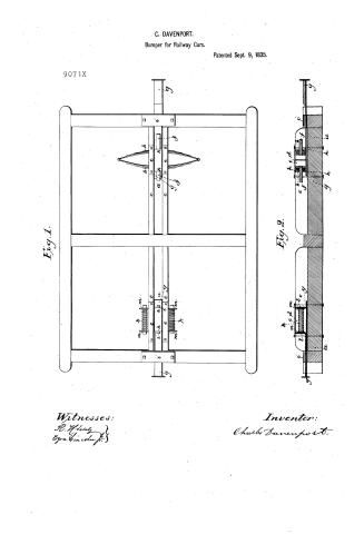
Charles Davenport's Patent Drawing for an Improvement in Railroad Cars

National Archives, Restored Patent Drawings (Record Group 241) · Full-size scan at the National Archives · Catalog record
Show the text on the drawing Hide (98 words)
Words on the drawing as machine-read by the National Archives; not checked. Useful mainly for searching.
CARS. / Buffer / -213 Rallway Dran Appliances, / CLASSIFICATION / Buffers / 9071X 9071X / Patent Sept. 9. 1835 / References. / DIVISION. / Fio 1. / all figs 102. is the perchar middle piece. / 1841 / h.h. / arethe elloptical springs / eccc. / - side planks. / d.d. / openings / e.e / straps. / f.f. / Knd.s. / That Bar / Whith / Square loop. / ii / niver har 88 / k.k.k. / spiral springs / of / 11 / Central Rod. / is / En. / is / 211,711, / end flut nars / Charles Improve / ment in / Chairsbanenport / Pat. Sept.9.1835 / Witnesses / R. Klew / Egradience / Figi2, / Drawing, from office of R.H. Edds.
USPTO scan
The patent as scanned by the USPTO
-
 Page 1
-
 Page 2
-
 Page 3
-
 Page 4


U.S. Patent and Trademark Office · Google Patents
Show the transcription Hide (1,214 words)
Machine transcription (LightOnOCR) of the pages as scanned by the USPTO, most of them the handwritten copies made when the records were restored after the 1836 fire. Not checked; it can misread handwriting, so compare it with the scan.
Page 1.
C. DAVENPORT.
Bumper for Railway Cars.
Patented Sept. 9, 1835.
9071X
Fig. 1.
Fig. 2.
Witnesses:
R. H. H.
Ezra Lincoln Jr.
Inventor:
Charles Davenport.
Page 2.
9-9-1835
Sept. 9, 1835
Charles Davenport Cambridge Mass. 9071X
Letters Patent
The schedule referred to in these Letters Patent, and making part of the same, containing a description in the words of the said Charles Davenport, himself, of his improvement in Rail Road Cars by means of Springs for easing the motion or shock produced at the moment of stopping or starting.
To all to whom these presents shall come, Be it known that I Charles Davenport of Cambridge in the county of Middlesex and State of Massachusetts have invented a new and useful improvement in Rail road Cars by means of Springs for easing the motion or shock produced at the moment of stopping or of starting, and that the following is a full and exact description of the construction and operation of the said machine as invented or improved by me.
My improvement is to be applied by connecting the cars, in such a manner as to ease the first shock of motion or rest, it is used between each couple, by being secured to the middle piece running through the frame of the carriage, or what is commonly termed the frame in coaches. The manner of constructing these springs and their requisite features, I conduct in the following manner. At about two and a half feet from the end of the middle piece and on the top thereof there occurs, it is in the direction of the width of the frame, two connected semi circular springs or, as they are known as elliptical ones by means of two pieces of plank of old time, which are held firmly on the middle piece one on each side. The springs are let into these pieces as low down as to be about flush with the top and there secured by means of a strap bolted across, and the opening is to be sufficiently long to admit the full play of the springs.
They are an inch semi circle, to consist of as many leaves as may be requisite for the strength, and through the centre of each an opening is to be made, to admit a rod of about six inches in length, through the whole thickness of leaves, which is to be inserted or otherwise secured on the inside so that the rod projects entirely from the outside of each elliptical half and stays firm. Along the bar or plank beneath these springs is to be a rod and slide back and
Page 3.
and furnished upon the middle piece and directly beneath them upon the top of the springs is also laid along another flat piece of sufficient length to embrace the whole dilatation or expansion of them, and also to allow its ends to be bent down the width of them, and then to be secured to the bar below them forming a square loop encircling the centre of them. A hole is to be made through each bent end of this loop directly opposite to the rod, and which is intended to play easily along backwards or forwards on this rod which is passed through it for that purpose.
The other end of the flat bar may at beyond the carriage frame as far as may be necessary, and has a pin or hook or other contrivance by which the connection with the other car is to be effected. In the operation of these springs the shock which for example we will suppose to be that of starting causes the end of the bar furnished with the hook or pin for connection to be drawn out in the foremost car. This of course brings back the square loop with it, causing it to press against the outside of the joint semicircle and thereby bringing back also at the same time the back or hinder spring pressing against the opening in the plank cannot recede, but the loop passes on along the rod by means of the opening left for that purpose and which rods must be equal in length to the play of the springs say 6" say in this case that the hole in the loop cannot pass over the ends of either rod. The reverse mode of operation will attain the other shock or that of stopping. A shape of square loop is also to be preferred to connecting ends of the bar so as to retain it in sliding in its proper position on the middle piece. These springs may be used to every car or only alternately.
The same effect may be produced by using spiral instead of the elliptical springs, and in this case the opening in the middle piece is made much longer, so as to admit a long spiral spring to be inserted therein having a sufficient coil in the end to receive a rod as long as the spring which keeps the coil straight. As many of these spring coils may be used as thought necessary but in general three will answer well one at each side and one in the middle. The long flat bar is the same to take the square loop but which must be as long as the opening or length of the springs. Through the hole in the middle is secured a rod by means of a thimble for the central spiral to contract on by the same length as the others. A short flat bar also fixed across the end of the square loop one at each end a from one side of the openings in the planks to the other.
Page 4.
9071X
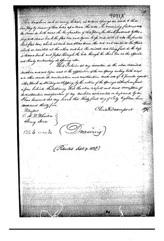
Then bars have each as many holes, as rods or springs are used, & these bars play by means of these holes up and down the rods. The remaining fixtures are the same in both cases. In the operation of this plan, the shock produced by the spring will draw back the flat bar and spring loop, and with it also the forward short flat bar, which at each end slides down the rod and contacts the spring which is resisted at the other end but the middle rod being fast in the top is drawn back and passes through the hole through the short bar at the opposite end thereby contracting its spring also.
That I claim as my invention in the above described machine and not before used is the application of the one spring acting both ways in other words the combination and construction made use of to provide against either shock in starting or stopping, by the action of the springs either from front or from behind. Intending that the above is a full and exact description of the construction and operation of my machine as invented or improved by me. I have hereunto set my hand this thirty-first day of July eighteen hundred and thirty-five.
Witnesses
C. H. H. Wharton
Henry Stine
1326 words
(Drawing)
(Patented Sept. 9, 1893)
Charles Davenport
19.
Published accounts: journal notice
Notice in the monthly list of patents
Journal of the Franklin Institute, new ser., vol. 16 (1835), p. 358 · View the page
534. Rail-road cars. Charles Davenport, Cambridge, Mass.
Published accounts: journal notice
Notice in the monthly list of patents
Journal of the Franklin Institute, new ser., vol. 17 (1836), p. 255 · View the page
14. For a mode of Relieving the Shock in the Stopping of Rail Road Cars; Charles Davenport, Cambridge, Middlesex county, Massachusetts, September 9.
About this record
- Patentee
- the Journal of the Franklin Institute, Journal
- Date
- the Name and Date index of patents, USPTO records, Jim Shaw's X-patent list
- Invention
- the Name and Date index of patents
- Listed in
- the Name and Date index of patents, USPTO records, Jim Shaw's X-patent list, the Journal of the Franklin Institute, Burke's List of Patents (1847)
- The patentee's full name comes from the Franklin Institute's journal.
- The residence comes from the Franklin Institute's journal.
- Burke's 1847 Patent Office list gives the same patent.