

Drawings and documents
USPTO scan
The patent as scanned by the USPTO
-
 Page 1
-
 Page 2
-
 Page 3
-
 Page 4


U.S. Patent and Trademark Office · Google Patents
Show the transcription Hide (1,058 words)
Machine transcription (LightOnOCR) of the pages as scanned by the USPTO, most of them the handwritten copies made when the records were restored after the 1836 fire. Not checked; it can misread handwriting, so compare it with the scan.
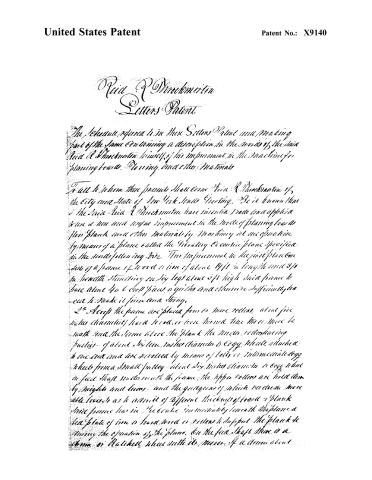
Page 2.
United States Patent
Patent No.: X9140
Paid & Described in Letters Patent
The Schedule referred to in these Letters Patent and making part of the same containing a description in the words of the said Paid & Described himself of his improvement in the machine for planing boards, flooring, and other materials.
To all to whom these presents shall come, We, the Secretary of the City and State of New York, do hereby declare that the said Paid & Described have invented and applied to use a new and useful improvement in the mode of planing boards, flooring, and other materials by machinery, as described by means of a plane called the Rotary Eccentric Plane, specified in the words following: Viz. This improvement is the first plane consisting of a frame of wood or iron of about 14 ft. in length and 3 ft. in breadth, standing on six legs about 5 ft. high. Said frame to have about 40 to 60 cross pieces, or girdles, and otherwise sufficiently braced to make it firm and strong.
2d. Across the frame are placed from 6 to 10 rollers, about five inches diameter, having a wood or iron rim, the same being made and the same as the plank the motion, rollers having pulleys of about 10 inches diameter or egg wheel, attached to one end and are revolved by means of belts or intermediate egg wheels from a small pulley about 5 inches diameter or egg wheel on fixed shaft underneath the frame; the upper rollers are held down by weights and levers, and the grooves of which receive more or less boards as to admit of different thicknesses of board or plank. Said frame has in the centre immediately beneath the plane a bed plate of iron or hardwood or rollers to support the plank during the operation of the plane, on the fixed shaft there is a drum or Ratchet wheel with its mover, if a drum about
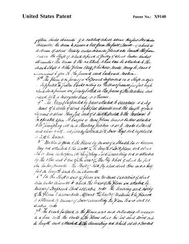
Page 3.
United States Patent
Patent No.: X9140
fifteen inches diameter of a ratchet wheel about two feet six inches diameter; the arm to receive a belt from the first Motor—(which is a Worm of about twenty inches diameter) placed at the lower end of the shaft of, which is fixed a pulley of about twelve inches diameter. The Worm to the ratchet wheel can be attached to the crank shaft or to the plane itself, whichever mode may be most convenient to give it the forward and backward motion.
3rd The plane is in form of a segment suspended on a shaft or axis—Supported on pillar blocks resting on Gallows frames perfect high which said frames are firmly fitted in the frame of the machine and braced with a triangular brace—or stanchion.
4th The Plane (suspended by straps attached to eccentrics) is a segment of a circle of about eight feet diameter and the length of plain segment is about three feet, and of a width suited to the material to be operated upon. It has five or more plane irons or cutters attached to its periphery set in a slanting position so as to make a smooth and clear cut and firmly fastened with iron keys and regulated in tilt to lines.
5th Motion is given to the plane by means of a flexible lever or connecting rod attached to the centre of the length of said plane and about 2½ or three inches from its periphery. Said connecting rod is attached by the other end to the arm of the fly wheel of about two feet six inches diameter—the shaft of said fly wheel about three and a half feet in length and 1½ in diameter.
6th To the shaft or axis of plane are the small eccentrics of about nine inches diameter to which the irons of the plane are attached by means of straps and short eccentric rods. The lowering and raising of the plane to accommodate different thickness of material to be planed is obtained by means of levers connecting the plane irons and eccentric rods.
7th The crank fastened to the plane axis and extending downwards in a line with the centre of the plane about two feet and three inches in length and attached to the connecting rod which at its other end
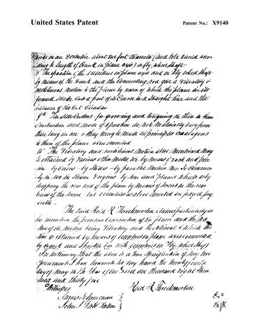
Page 4.
United States Patent
Patent No.: X9140
Works on an Eccentric about the foot Channels (Area to be varied according to length of Crank or plane axis) in fly wheel shaft.
The operation of the Eccentrics on plane axis and on fly wheel shaft by means of the Crank and the Connecting Rod give a Vibratory & Rectilinear Motion to the Plane by reason of which the plane in its forward stroke cuts a part of its Course in a Straight line and the Balance of the Cut Circular
4th The Side Cutters for grooving and tonguing in their Construction and Mode of Operation do not Materially vary from those long in use so they may be made on principles analogous to those of the plane above described
11th The Vibratory and Rectilinear Motion above Mentioned may be obtained by various other Modes, viz by means of rack and pinion - by Crank - by Shias - by parallel Motion now so Commonly in use in Steam Engines - by Sun and Planet Wheels, or by dipping the rear end of the plane by means of Joints in the rear haw of the same - but Eccentrics as above described are judged preferable -
The said Reids & Throckmorton claim particularly as so invented the peculiar Construction of the plane and the Manner of its Motion being Vibratory and Rectilinear to which Motion is obtained by means of Eccentrics on plane axis connected by Crank and Shackle bar with Eccentrics on Fly wheel Shaft
In testimony that the above is a true Specification of the Invention I have hereunto set my hand the twenty fourth day of May in the Year of our Lord one thousand eight hundred and thirty five
Witnesses
James Schumman 3
John J. Park & Dabie 3
Reid & Throckmorton
E. O.
Ch. J. H.
Published accounts: journal notice
Notice in the monthly list of patents
Journal of the Franklin Institute, new ser., vol. 17 (1836), p. 70 · View the page
592. Planing Boards, &c. -Reid R. Throcmorton, New York,
Published accounts: journal notice
Notice in the monthly list of patents, with remarks
Journal of the Franklin Institute, new ser., vol. 17 (1836), p. 326 · View the page
4. For a Planing Machine; Reid R. Throckmorton, city of New York, October 6.
Remarks. This machine differs from those which have preceded it to such an extent as, in our opinion, to merit the character of novelty; that of utility it must acquire, if at all, by its actual performance. The general arrangement of the apparatus only, is shown by the specification and drawing; but, if constructed from these, most of the details would have to be invented by the builder, as the information given is very defective in this respect. The plane is to be about three feet long, and its face is to be a segment of a circle, of about eight feet in diameter, and there are to be seven, or more, plane irons, or cutters, extending from it, of such width as may be necessary. To the upper part of the plane, a rod, or shackle bar, is attached, the other end of which is moved by a crank, thus causing the plane to traverse, or rather to vibrate, backward and forward, with a rocking, or curved, motion. How the cutters are to be kept upon the plank, and caused to cut to a proper depth, does not appear, as, in the drawing, they are represented as standing out like knives, far below the face of the plane. Tongueing and grooving is to be effected in a similar way, by cutters operating laterally, and moved by a crank. The claim is to "the peculiar construction of the plane, and the nature of its motion, being vibratory and rectilineal," &c. There must be more in this machine than is described in the specification, or than meets the eye in the drawing, or it will be found of little value.
About this record
- Patentee
- the Journal of the Franklin Institute, Journal
- Date
- the Name and Date index of patents, USPTO records, Jim Shaw's X-patent list
- Invention
- the Name and Date index of patents
- Listed in
- the Name and Date index of patents, USPTO records, Jim Shaw's X-patent list, the Journal of the Franklin Institute, Burke's List of Patents (1847)
- The patentee's full name comes from the Franklin Institute's journal.
- Burke's 1847 Patent Office list gives the same patent.