

Drawings and documents
National Archives restored drawings: drawing
M. Davenport's Patent Drawing for a Machine for the Production of Horse Power

National Archives, Restored Patent Drawings (Record Group 241) · Full-size scan at the National Archives · Catalog record
Show the text on the drawing Hide (106 words)
Words on the drawing as machine-read by the National Archives; not checked. Useful mainly for searching.
185. MECHANICAL MOTORS. / Horse-Powers, / Treads. / 42 / VI O DAVENPORT / Patenled / 10/01/1835 / clauslizuation / 9149- / Horse Power / Section of Cylinder Heard / a Frame / b. Cylender-B. Heads of go / C. Bar forming looth or cog / d. Large Pulley / c. Crossnecce supporting RollersE / f Jointernlalform. F Main Zars 019 / I Stale of bent Iron and square link G / h. Diamond shapell Cleats / Geba oftending / begin 4 emotional / form tealt / the the plank and / and work / Patent office October 31" 1841 / Made under the dinetion of the communer / Stricklancs Del / of Patents in conformity with act of 3' March 1337 / Commissioner of Tatents
USPTO scan
The patent as scanned by the USPTO
-
 Page 1
-
 Page 2
-
 Page 3
-
 Page 4
-
 Page 5


U.S. Patent and Trademark Office · Google Patents
Show the transcription Hide (1,547 words)
Machine transcription (LightOnOCR) of the pages as scanned by the USPTO, most of them the handwritten copies made when the records were restored after the 1836 fire. Not checked; it can misread handwriting, so compare it with the scan.
Page 1.
No Printed Specification Available
9149X
M. Davenport,
Horse Power.
Patented Oct. 10, 1835.
AM. PHOTO-LITHO. CO. N.Y. (OSBORNE'S PROCESS)
Page 2.
9149X
Oct 10, 1835
281
Moses Davenport's
Letters Patent
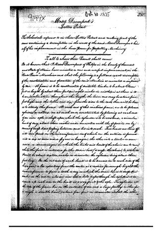
The Schedule referred to in these Letters Patent and making part of the same containing a description in the words of the said Moses Davenport himself of his improvement in the horse power for propelling machinery.
To all to whom these Presents shall come
Be it known that I, Moses Davenport of Philips in the County of Somerset and State of Maine have invented a new and useful improvement in the "Horse Power" Machine and that the following is a full and exact description of the construction and operation of the said Machine as invented or improved by me. A frame is to be constructed of suitable timber to be about Eleven feet in length by about three feet (and eight inches) in width (and as there is to be an inclination throughout the length, the lower end may be about five feet high and the taller one six; from the sides to the ends there will be braces to steady the frame). At each end of this inclined frame, are to be placed cylinders or rollers, one at each end, constructed by placing at each end of an iron axle or shaft upon which the cylinder is to be revolved, a circular head of say about three inches wide connected with the opposite one by means of rope bars passing between and let into each. These heads are laid off into two parts on the circumference, one of which on the outside is formed into a six or nine sided figure or hexagon, the other into a twelve or more sided or dodecagon on which the links and bands of the chain are to run, while the first is intended for the main bar (a rope or chain) to work on. It will be about sixteen inches in diameter, the cylinder being about three feet long. On the outside of each head is to be secured on to each side of the hexagon, a bar extending from the centre as a radius far enough beyond the circumference to form a tooth or cog on which the main bar is to drop (and work); on the inside also an iron rod or bolt passes through the axle and is secured up each side on the head as a stay for it & the axle. The cylinder at the top of the frame has on the outside of one end a large pulley either for a single or double band about four feet in diameter and at the other
Moses Davenport
Page 3.
282. 9149X
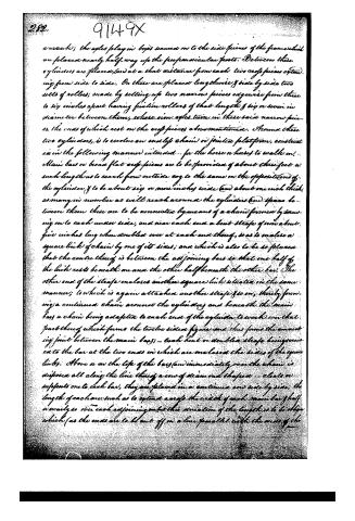
a walk; the axles play in boxes secured on to the side pieces of the frame which are placed nearly half way up the perpendicular posts. Between these cylinders are planes, (and at a that distance from each two cross pieces extending from side to side. On these are placed lengthwise & side by side two sets of rollers; made by setting up two narrow pieces edgewise from three to six inches apart having friction rollers of that length & six or seven in diameter between them, whose iron axles turn in these said narrow pieces, the ends of which rest on the cross pieces above mentioned. Around these two cylinders, is to revolve an endless chain or jointed platform, constructed in the following manner intended... for the horse or horses to walk on. Main bars or broad flat cross-pieces are to be provided of about three feet in such length as to reach from outside edge to the same on the opposite end of the cylinder & to be about six or more inches wide (and about one inch thick, as many in number as will reach around the cylinders and space between them these are to be connected by means of a chain formed by screwing on to each under side, and near each end a bent strap of iron about five inches long when doubled over at each end thereof, so as to make a square link of chain by one of its sides; and which is also to be so placed that the centre thereof is between the adjoining bars so that one half of the link rests beneath one and the other half beneath the other bar. The other end of the strap encloses another square link situated in the same manner; to which is again attached another strap & so on, thereby forming a continued chain around the cylinders and beneath the main bars a chain being adapted to each end of the cylinder to work over that part thereof which forms the twelve sided figure and thus forms the connecting joint between the main bars;—Each bent or doubled strap being screwed to the bar at the two ends in which are enclosed the sides of the square links. Above or on the top of the bars (and immediately over the chain) is affixed all along the line thereof a row of steam and shaper cleats or supports one to each bar, they are placed in a continuous row side by side, the length of each one such as to extend across the width of each main bar half nearly so over each adjoining one but the sum of the lengths is to be about which (as the ends are to be cut off in a line parallel with the ends of the
Page 4.
main bars) give the diamond appearance. Each cleat is attached to its bar by two screws which are to be one (and) the same as those used to fasten on the double straps—the screws being long enough to go through the straps, the bar of the cleat, (and) in this way I form & support an endless chain or jointed platform which is able to rest on the double row of friction rollers bearing against the under side of the top part of this chain or platform. Between two ergo pieces forming the tops at the ends of the main frame is laid parallel with the sides, two long bars at a sufficient distance apart for a horse to travel between them & to reach about as high as his sides intended to secure the breathing) to & to steady his motions, or it may be adapted for many). The end of each main bar of the platform, have a sufficient width mortised out of the centre to receive the ergo on the outside of the head, to drop into them as the platform moves on which ensures the turning of the cylinders. Operation. The horse or horses, being placed on the platform & secured to the breathing hooks, the motion produced by walking or travelling bars placed on the tops of the main bars to prevent them from wear sets the jointed platform in motion (and) the weight of the animal power is sustained by the double set of friction rollers beneath, & also by the diamond cleats above the platform. The links connected by the cross straps form a chain of joints to the main bars (and) revolve round the two-sided figure of the cylinder heads while the ergo which project from these heads are caught by the mortises in the main bars (and) consequently brought round with them which gives the desired motion to the said cylinders. A leather belt may be used instead of the chain & fastened on to the main bars by means of two screws in the same line of the length of the bars situated near the front edge of the mortise; so that first presented to the ergo so as to keep it down steady to the ergo & each belt has that part of the head it is to work over made into a circular form, the strength of it being equal (where two are used) to about that of a thorough brace & a carriage spring (and) the width may be from two to three inches & small pieces of sheet iron at the insertion of each seen head in order to prevent its tearing through the leather. The front cylinder applies motion to the crank at one end & to the band wheel at the other by which the power is continued on to the machinery intended to be driven.
Page 5.
284. 9149X
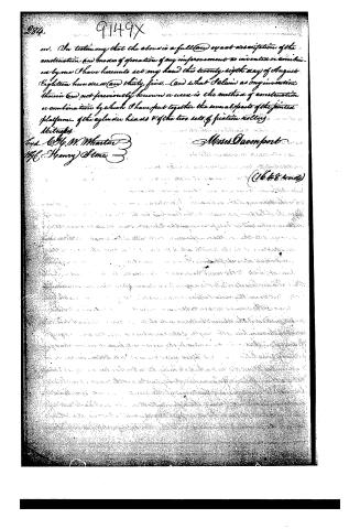
In testimony that the above is a full and exact description of the construction and modes of operation of my improvement as invented or combined by me I have hereunto set my hand this twenty ninth day of August Eighteen hundred and thirty five. And what I claim as my invention therein and not previously known or used is the method of construction or combination by which I have put together the several parts of the jointed platform of the cylinder heads & of the two sets of friction rollers.
Witnesses
T. H. M. Wharton
H. Henry Stone
Moses Davenport
(1648 lines)
Published accounts: journal notice
Notice in the monthly list of patents
Journal of the Franklin Institute, new ser., vol. 17 (1836), p. 70 · View the page
605. Horse Power.-Moses Davenport, Philips, Somerset County, Maine,
Published accounts: journal notice
Notice in the monthly list of patents, with remarks
Journal of the Franklin Institute, new ser., vol. 17 (1836), p. 329 · View the page
17. For a Horse Power; Moses Davenport, Phillips, Somerset county, Maine, October 10.
Remarks. The claim under this patent is to "the method of construction, or combi31* nation, by which the several parts of the jointed platform are put together; of the cylinder heads, and of the friction rollers." This combination in most of its parts, exists in numerous other endless platforms; the peculiarities of the one before us, ought, therefore, to have been pointed out, as upon these alone could any valid claim be founded.
About this record
- Patentee
- the Journal of the Franklin Institute, Journal
- Date
- the Name and Date index of patents, USPTO records, Jim Shaw's X-patent list
- Invention
- the Name and Date index of patents
- Listed in
- the Name and Date index of patents, USPTO records, Jim Shaw's X-patent list, the Journal of the Franklin Institute, Burke's List of Patents (1847)
- The patentee's full name comes from the Franklin Institute's journal.
- The residence comes from the Franklin Institute's journal.
- Burke's 1847 Patent Office list gives the same patent.