

Drawings and documents
National Archives restored drawings: drawing
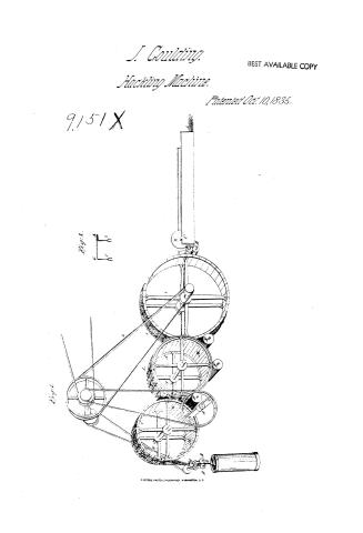
John Goulding's Patent Drawing for a Machine for Hatchelling Tow

National Archives, Restored Patent Drawings (Record Group 241) · Full-size scan at the National Archives · Catalog record
Show the text on the drawing Hide (35 words)
Words on the drawing as machine-read by the National Archives; not checked. Useful mainly for searching.
$256 / JOHN COULDINC'S / 18.|BRAKES & GINS. / Hackling Machines. \ / Machine for Hatchelling Tow. / CEALLILLATION / tig. / wig2 / Palented 10th October 1035.00 / I,
USPTO scan
The patent as scanned by the USPTO
-
 Page 1
-
 Page 2
-
 Page 3
-
 Page 4
-
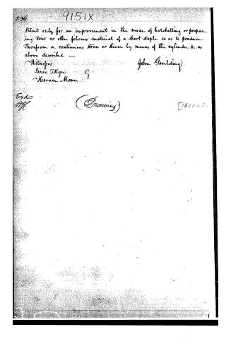 Page 5


U.S. Patent and Trademark Office · Google Patents
Show the transcription Hide (1,433 words)
Machine transcription (LightOnOCR) of the pages as scanned by the USPTO, most of them the handwritten copies made when the records were restored after the 1836 fire. Not checked; it can misread handwriting, so compare it with the scan.
Page 1.
J. Goulding.
Hacking Machine.
Patented Oct. 10, 1835.
BEST AVAILABLE COPY
9,151 X
Fig. 1.
Fig. 2.
Page 2.
9151X Oct 10 1855 293
John Goulding, of Boston, Mass:
Letters Patent
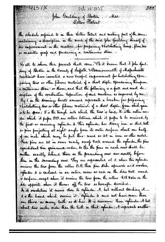
The schedule referred to in these Letters Patent and making part of the same, containing a description in the words of the said John Goulding himself, of his improvement in the machine for preparing hatchelling hemp, flax, tow or manilla grass and producing a continuous strand.
To all to whom these presents shall come: Be it known that J. John Goulding of Boston in the County of Suffolk & Commonwealth of Massachusetts machinist have invented a new & useful improvement for hatchelling & preparing tow or other fibrous material of a short staple & producing therefrom a continuous strand or thread, and that the following is a full and exact description of the construction & operation of said machine as improved by me.
Fig. 1 in the drawings hereto annexed represents a breaker for preparing hatchelling tow or other fibrous material of a short staple from which yarn is to be spun; I is the trough into which the tow is laid, K is the roller under which it passes. B.B. are rollers between which it passes to be received by the first or receiving cylinder A. This cylinder has strong iron or steel teeth or pins projecting at right angles from its outer surface about one half of an inch which may be put thro’ wood or set in iron or other metal. These pins are set in rows nearly across & all around the cylinder, the pins equidistant & in quincunx order, so the the pins in each row shall be neither exactly behind those on the preceding row nor exactly before them in the succeeding row. They are represented at 5. where this cylinder receives the tow from the rollers B.B. these pins strike upwards as it revolves, cylinder A is enclosed in an entire cover or case on the sides & all round its surface, except where it receives the tow from the rollers B.B. & also on the side opposite where it throws off the tow as hereafter described.
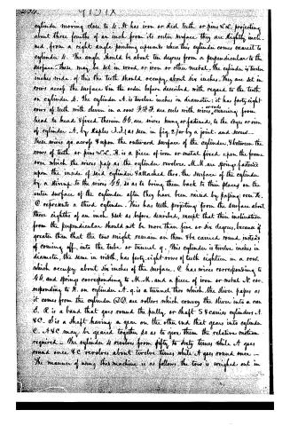
In its revolution, it moves close to cylinder A, but without touching it — 6 is the band which carries it. Cylinder A need not have more than one third as many teeth as it has. It is narrower than cylinder A but about two inches wider than the teeth in that cylinder; A represents another
Page 3.
cylinder moving close to 4. It has iron or steel teeth or pins 2a, projecting about three fourths of an inch from its outer surface; they are slightly inclined, from a right angle pointing upward, when this cylinder comes nearest to cylinder 4. The angle should be about ten degrees from a perpendicular to the surface. These may be set in wood or iron or other metal. The cylinder is twelve inches wide; of this the teeth should occupy about six inches. They are set in rows across the surface in the order before described with regard to the teeth on cylinder 4. The cylinder 4 is twelve inches in diameter; it has forty-eight rows of teeth with eleven in a row. 33. F. are reels with wires, running from head to head. 4 fixed therein 33. are wires hung or fastened to the edges or rim of cylinder 4, by staples 33. (as seen in fig. 2) or by a joint and screw. These wires go across 4 upon the outward surface of the cylinder, 4 between the rows of teeth or pins 2a. H. is a piece of iron or metal fixed upon the frame over which the wires pass as the cylinder revolves. M. M. are springs fastened upon the inside of said cylinder 4 attached thro. the surface of the cylinder by a string to the wires 33. so as to bring them back to their places on the outer surface of the cylinder after they have been raised by passing over H. C represents a third cylinder. This has teeth projecting from the surface about three eighths of an inch 4 set as before described, except that their inclination from the perpendicular should not be more than five or six degrees, because if greater than that the tow might remain on them 4 be carried round instead of coming off, into the tube or tunnel q. This cylinder is twelve inches in diameter, the same in width, has forty-eight rows of teeth eighteen in a row, which occupy about six inches of the surface. C has wires corresponding to 33. and springs corresponding to M. M. and a piece of iron or metal N. corresponding to H. on cylinder 4. q. is a tunnel thro which the sliver passes as it comes from the cylinder 33. D. are rollers which convey the sliver into a can C. R is a band that goes round the pully or shaft S 4 carries cylinders 4. 4C. S is a shaft having a gear on the other end that gears into cylinder C. 4 4C may be geared together so as to give them the relative motion required. The cylinder 4 revolves from fifty to sixty times while 4 goes round once 4C revolves about twelve times while 4 goes round once. The manner of using this machine is as follows, the tow is weighed out in
Page 4.
9157X
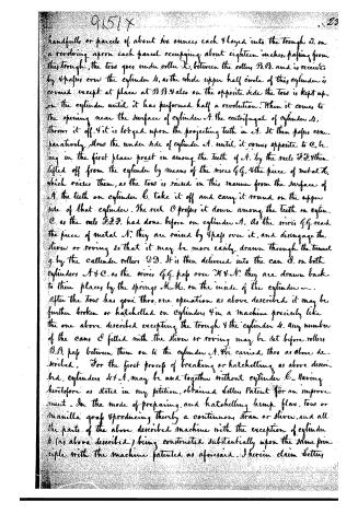
handfuls or parcels of about six ounces, each 4 layed into the trough J. on a revolving apron each parcel occupying about eighteen inches, passing from this trough, the tow goes under roller X, between the rollers B.B. and is received by 4prizes over the cylinder A, as the whole upper half circle of this cylinder is covered except at places at B.B. 4 also on the opposite side the tow is kept up on the cylinder until it has performed half a revolution. When it comes to the opening near the surface of cylinder A, the centrifugal of cylinder A, throws it off. 4 it is lodged upon the projecting teeth in A. It then passes comparatively, down the under side of cylinder A. until it comes opposite to C, being in the first place pressed in among the teeth of A, by the reels F.F. 4 then lifted off from the cylinder by means of the wires G.G. 4 the piece of metal H, which raises them, as the tow is raised in this manner from the surface of A, the teeth on cylinder B, take it off and carry it round on the upper side of that cylinder. The reel O presses it down among the teeth on cylinder C, as the reels F.F.F. had done before on cylinder A. As the wires G.G. reach the piece of metal N, they are raised by 4prizes over it, and disengage the sliver or roving so that it may be more easily drawn through the tunnel g, by the callender rollers D.D. It is then delivered into the can E, on both cylinders A & C, as the wires G.G. pass over N & N, they are drawn back to their places by the springs M.M. on the inside of the cylinders.
After the tow has gone thro. one operation as above described it may be further broken or hatchelled on cylinder 4 in a machine precisely like the one above described excepting the trough 4 the cylinder A. Any number of the cans E filled with the sliver or roving may be set before rollers B.B. pass between them on to the cylinder A. 4 are carried thro as above described. For the first process of breaking or hatchelling as above described, cylinders A & A, may be used together without cylinder B. Having heretofore as stated in my petition, obtained Letters Patent for an improvement in the mode of preparing, and hatchelling hemp flax, tow or manilla grass 4 producing thereby a continuous strand or sliver, and all the parts of the above described machine with the exception of cylinder A (as above described) being constructed substantially upon the same principle with the machine patented as aforesaid. I herein claim Letters
Page 5.
296. 9151X
Patent only for an improvement in the mode of hatching or preparing tow or other fibrous material of a short staple so as to produce therefrom a continuous strand or sliver by means of the cylinder as above described —
Witnesses:
Isaac Thyn
Horace Mann
John Goulding
(Drawing)
1600 w. 2.
About this record
- Patentee
- Jim Shaw's X-patent list
- Date
- the Name and Date index of patents, USPTO records, Jim Shaw's X-patent list
- Invention
- the Name and Date index of patents
- Listed in
- the Name and Date index of patents, USPTO records, Jim Shaw's X-patent list, Burke's List of Patents (1847)
- Burke's 1847 Patent Office list gives the same patent.