

Drawings and documents
USPTO scan
The patent as scanned by the USPTO
-
 Page 1
-
 Page 2
-
 Page 3
-
 Page 4
-
 Page 5
-
 Page 6
-
 Page 7
-
 Page 8
-
 Page 9
-
 Page 10
-
 Page 11
-
 Page 12


U.S. Patent and Trademark Office · Google Patents
Show the transcription Hide (4,647 words)
Machine transcription (LightOnOCR) of the pages as scanned by the USPTO, most of them the handwritten copies made when the records were restored after the 1836 fire. Not checked; it can misread handwriting, so compare it with the scan.
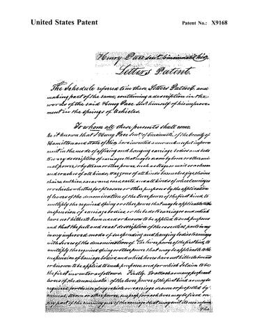
Page 2.
United States Patent
Patent No.: X9168
Henry Pace, Cincinnati, Ohio
Letters Patent.
The Schedule referred to in these Letters Patent, and making part of the same, containing a description in the words of the said Henry Pace himself of his improvement in the springs of vehicles.
To whom all these presents shall come,
Be it known that I Henry Pace, of Cincinnati, of the county of Hamilton and state of Ohio, have invented a new and useful improvement in the mode of affixing and hanging carriage bodies and beds to every description of carriages that may be drawn by horse or other animal power, or by steam or other power, such as stage or mail coachman and coaches of all kinds, wagons of all kinds, barouches, gigs, chaises, chairs, sulky, carriages, cabs, carts, and all kinds of wheel carriages or vehicles whether for pleasure or other purposes by the application of levers of the denomination of the lever power of the first kind, to multiply the required spring or other power that may be applicable to the suspension of carriage bodies, or the beds to carriages and which have not hitherto been used or known to be applied to such purposes and that the full and exact description of the essential parts in my improved mode of suspending and hanging bodies to carriages with levers of the denomination of "the lever power of the first kind, to multiply the required spring or other power that may be applicable to the suspension of carriage bodies, and which levers have not hitherto been or known to be applied to such purposes, and for which I claim to be the first inventor as follows. Firstly, To attach as many separate levers of the denomination of the lever power of the first kind as may be required for the use of any vehicle or carriage drawn or propelled by animal, steam or other power, such as for each lever may be fixed on any part of the running gear of the carriage that may suit its use or form.
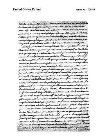
Page 3.
United States Patent
Patent No.: X9168
the levers to work free, the fulcrum to be placed at any point of the line between the weight and the power, at the option of the builder, secondly. To attach one or more springs or other applicable power, to each lever, one end of each spring or springs to be affixed either to the bottom of the body or bed, or to the running gear, and the other end of each spring or springs or other power, to be attached to the end of the long arms of the levers so to work free, or to the running gear.
Thirdly. To attach the ends of the short arms of all the levers to the body shackles, or to the body or carriage bed (which is the weight) so that the levers and springs may work free when the carriage is in motion. In forming my improved mode of hanging carriage bodies to the running gear of carriages with levers of the denomination of the first kind, I employ these my essential points according to convenience, which admits of various modifications as to form and proportions each as must be and are quite familiar to every competent carriage manufacturer and therefore it will be sufficient for the perfect description of my improved principle of hanging carriage bodies to the running gear of carriages with the levers of the first kind, that I explain some of the modes of forming and combining the essential points of my invention with the other parts of the variety of carriages and of fashions and modes which may be familiar in the work shops. Model. 6. Four wheel carriages. Levers to project under the body. Flat springs, either linear, elliptic or otherwise affixed to the body at each end of the bottom. Suppose a carriage to admit of levers from two or up to twelve feet in length, more or less, but say for example that it shall be five feet. Place the fulcrum at the option of the manufacturer, which may be one sixth of the length of the lever; this gives the short arm ten inches in length, the long arm from five to ten inches. Then fix two props in the place of jacks or springs on the back of the carriage on the axle bed and spring bar, and two props on the front of the carriage in the same way, but the front props and levers must stand in a line of two or three inches (more or less as required) from the side of the body and towards the perch to give room for the levers to work side by side & to give room for the ends of the long arms of the levers.
Page 4.
United States Patent
Patent No.: X9168
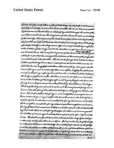
levers to pass each other without sticking. Each leaf is to have a mortise on its top, to admit a lever on each. The lever to be secured at its fulcrum in the mortise on its leaf by a bolt through the sides of the mortise and the lever. The long arms of the levers to slope under the body of the carriage. The long arms of the back levers to point towards the front and the front levers to point towards the back of the carriage to meet the springs of perhaps twenty inches long more or less. One end of each spring is affixed to the bottom of the body next to the shackle, one spring or more as required to each lever. The end of the long arms of the levers will, the springs at the fore part of the carriage to be bolted on at the corner of the body in the usual place for the shackles. The two back springs to be bolted in the bottom of the body two or three inches from the sides at the corners so that the levers may pass each other without sticking. A single or double lineal spring or more added together or an elliptic, to apply to each lever, one end of each spring or springs to each lever then bolted on to the bottom of the body is sloped down for its other end to be about five or six inches below the bottom of the body sufficient to give play for the levers and spring to work up and down without sticking the bottom of the body. The end of the long arm of each lever to meet the end of each spring in a line under the spring to be attached to it by an oblong square link to work free. The link attaches the spring and lever together and may be two or three inches long as required for the levers to move in the arcs of their circles by the combined movement of the spring, the lever and the link. If the weight is much the spring above described may have a lineal or spring of short dimensions riveted on to its end similar to that on the key to a bolt. This small spring to slope its other end to bear against the bottom of the body at which place a plate of brass will prevent wear. The short arm of each lever to be attached to the body by knotted hinge or otherwise to the shackles, to work free. If the front wheels of the carriage are intended to turn under the body, then all the props, the levers, the springs and the shackles (or other attachments in lieu of shackles) are placed nearer or near or near to the perch as may be required to remove them from contact with the wheels. These levers are also calculated to have
Page 5.
United States Patent
Patent No.: X9168
have the thick end of the flat spring or springs affixed near their one to the end of the long arms of each lever (in lieu of fixing the spring to the body) so that the other end of the spring shall reach near to the axle bed to which it may be attached by means of a staple and an oblong square link. If the levers are made of iron part of the long arm of each may be made of steel to spring towards the end; and the end of the spring to be attached to the bolster as above; or the spring may be riveted on the lever. The spring may be much longer than when attached to the body, and made more springy. If the lever is made of wood the same principle can be continued with mode VII. and mode VII. will answer well to combine with this mode I. [See mode VII].
The end of a lever (one foot long) rises in its ascent or descends in its inches, nearly one and a half inch from a perpendicular line by the motion of the lever in the arc of its circle; one of two feet rises 7/8 of an inch in the ascent of six inches one of three feet ascends nine sixteenths of an inch, one of four feet ascends sixteenths, one of five feet, one third of an inch. As the short arms of the lever, will have but little rise and fall the play of the gearing when in motion may answer to the motion of the lever in the arc of its circle; or a motion of an inch more or less required can be made in each of the front levers in lieu of the hole for the bolt of the fulcrum by which the front levers will slide backwards and forwards to the motion of the short arms in the arcs of their circles. The long arms are allowed for their motions in their arcs of circles by an extra length of link which attaches each to its respective spring. The patentee might here have rested his right to hang carriage bodies with levers of the first kind; but he has added the following variety of modes in his new application of the principle, a principle which is so well calculated to amalgamate with the spirit and knowledge of the times, and with the progressive increase of the most fanciful and brilliant embellishments.
Mode II. Four wheel carriages with levers to project under the body. Flat springs affixed to the running gear. The prop levers and shackles to be affixed or attached agreeably to the mode and principle mentioned in mode I. with the following variations viz. The axle, etc. or lineal spring
Page 6.
United States Patent
Patent No.: X9168
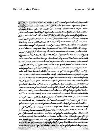
Spring on and across the midway of the length of the perch. Fix another directly under the perch and across it with the horns or points of the springs to horn up (or down) the same as the upper one if elliptic. Place a bolt through the top of the perch and the two elliptics in their centres to hold both fast. The two elliptics will then form half elliptics on each side of the perch and are prepared to connect with the ends of the two long arms of the two back levers. Fix two more elliptics in some manner across the perch, side by side with the first two for the two front levers; they are then prepared to be attached to the two long arms of the first levers by links as described in Model 1, with this difference that this lever, with the springs affixed to the running gear, will work over the springs to which they are attached; and also the levers are shorter and do not pass each other as in model 1, but reach only to the springs at the midway of the perch. Also the levers and props are affixed at the four corners of the running gear; as also all the shackles to the four corners of the body. If the front or wheels are to turn under the body the hind levers and props may remain as they are, but the front props and levers are to be placed triangularly that is, the ends of the short arms of the front levers are at their opposite shackle at the corner of the body and the ends of the long arms to go near and point to the side of the perch; but the props and shackles are to be fixed in a line to the levers. The springs if flat to be affixed on the perch, in a line with the levers to be attached to them as before; or a spiral spring can be attached to the perch one or more on each side, or if this shall not combine with the form or fashion of the carriage, then the front levers with their props and shackles may be placed nearer or near to the perch. In this case a short beam is fixed across and under the perch to which it is to be bolted about one foot from the axle tree or rather at a proper distance from the horns or horn bars to prevent their collision. A linear or other spring or springs are then affixed to one end of the end of bar, the same to the other end, and each spring or springs if flat to project in a line with and under their respective levers to the end of the front long arms.
Page 7.
United States Patent
Patent No.: X9168
or in line of a bar the springs maybe affixed at their thick ends to the axle bed or any part of the front gearing that may be applicable, but then the springs will have to be as long as the long arms of the front levers to extend in a line underneath to be united to their ends but it is to be considered whether the weight be carried (if it is great) will not force the axle bed on the bottom end of the springs from their fixtures. — Mode III. — How wheel carriages with levers to project under the body. Spiral springs attached to the running gear. Bolt two bars across and under the bench at midway of its length, side by side of each other. The springs to be attached by the middle to the four ends of the two bars and to stand upright with their mid lengths one half below the bar, the other above to give space for the play of the levers. The ends of the bars to be made to line with the ends of the long arms of the levers. one or more springs maybe attached to each end of the two bars (or 4 arms) in a position to work to the levers; The mid of the long arms of the levers to end to the spring to which they are to be attached as in mode II. If the front wheels are to turn under the body pursue the described mode of II. by shortening the front bar which contains the front spiral springs. The spiral springs maybe made enclosed with caps used poles for props; in lieu of a cylinder which is apt to clog with the dust of the roads; The spring is worked by a piston introduced down its middle with a cap fixed to the bottom end of the piston and a ring at the upper end. The ring to be attached to the end of the long arm of the lever to work free.
Mode IV. — How wheel carriages. Upright Levers. Spiral springs attached to the running gear. Six props on the axle bed as one at each corner of the carriage. Each prop to be formed by fixing two posts set sufficiently apart to admit the lever to be placed between them. The props may be twenty eight inches long more or less as the carriage may admit. The levers thirty two more or less. The levers to be placed upright to work backwards and forwards between the posts or props, and suspended by a bolt placed through the sides of the
Page 8.
United States Patent
Patent No.: X9168
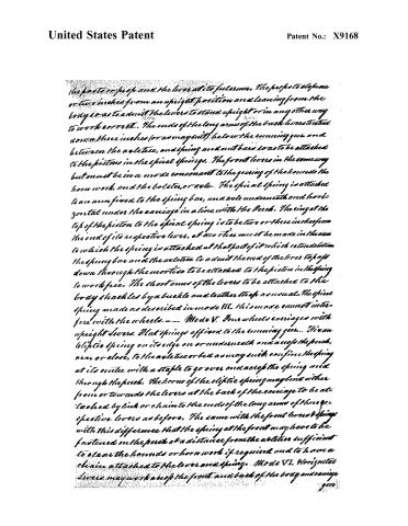
the parts of the body and the lever at its fulcrum. The parts to slope one or two inches from an upright position and leaning from the body so as to admit the levers to stand upright or in any other way to work correct. The ends of the long arms of the back levers extend down three inches (or as may suit) below the running gear and between the axle tree, and spring and nut bars so as to be attached to the pistons in the spiral springs. The front levers in the same way but must be in a mode consonant to the gearing of the horse or the horn work, and the bolster, or axle. The spiral spring is attached to an arm fixed to the spring bar, and a rule underneath and horizontal under the carriage in a line with the perch. The ring at the top of the piston to the spiral spring is to be two or three inches from the end of its respective lever, and no tie must be made in the arm to which the spring is attached at that part of it which extends from the spring bar and the axle tree to admit the end of the lever to pass down through the mortise to be attached to the piston in the spring to work free. The short arms of the levers to be attached to the body shall be by a buckle and leather strap as usual. The spiral spring made as described in mode III. This mode cannot interfere with the wheels. — Mode V. Four wheels carriages with upright levers. Flat springs affixed to the running gear. Fix an elliptic spring on its edge on or underneath and across the perch, near or close, to the axle tree or bed as may suit, confine the spring at its centre with a staple to go over and across the spring and through the perch. The horns of the elliptic spring may be either from or towards the levers at the back of the carriage to be attached by link or chain to the ends of the long arms of the respective levers as before. The same with the front levers & spring with this difference that the spring at the front may have to be fastened on the perch at a distance from the axle tree sufficient to clear the horns or horn work if required and to have a chain attached to the lever and spring. Mode VI. Horizontal levers may work across the front and back of the body and carriage gear.
Page 9.
United States Patent
Patent No.: X9168
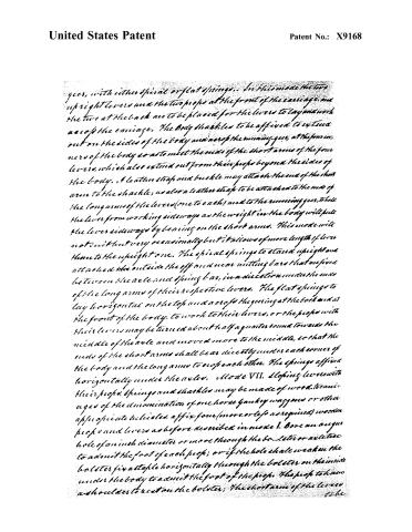
geer, with either spiral or flat springs. In this mode the two upright levers and the two props at the front of the carriage, and the two at the back are to be placed for the levers to lay and work across the carriage. The body shall be to be affixed to extend out on the sides of the body and across the running geer, at the four corners of the body so as to meet the ends of the short arms of the four levers, which also extend out from their props beyond the sides of the body. A leather strap and buckle may attach the end of the short arm to the shackle; as also a leather strap to be attached to the end of the long arms of the levers (one to each) and to the running geer, to hold the lever from working sideways as the weight in the body will pull the lever sideways by leaning on the short arms. This mode will not suit but very occasionally but it allows of more length of lever than to the upright one. The spiral springs to stand upright and attached outside the off and near nutting bars that are fixed between the axle and spring bar, in a direction under the ends of the long arms of their respective levers. The flat springs to lay horizontal on the top and across the geering at the back and at the front of the body, to work to their levers, or the props with their levers may be turned about half a quarter round towards the middle of the axle and moved more to the middle, so that the ends of the short arms shall bear directly under each corner of the body and the long arms to enclose each other. The springs affixed horizontally under the axles. Mode VII. Sloping levers with their props, springs and shackles may be made of wood, to an age of the denomination of one horse fancy waggons or other appropriate vehicles, affix four (more or less as required) wooden props and levers as before described in mode I. Bore an augur hole of an inch diameter or more through the bolster or axle tree to admit the foot of each prop; or if the hole shall weaken the bolster fix a staple horizontally through the bolster on the inside under the body to admit the foot of the prop. The prop to have a shoulder to rest on the bolster; the short arm of the lever to be
Page 10.
United States Patent
Patent No.: X9168
to be attached to the body by wooden hinges or to a tow hook. See: the levers to run the whole length of the perch, between the front and back axles. The thick ends of the springs to be bolted on to the bottom of the body at its front (the same same behind) immediately over their respective levers. A bolt to go through both shackle and spring together, to attach them to the body, and the other end of the spring to extend with the whole length of the lever, and both lever and spring to be attached together by an oblong link, the lever to work under the spring, and both to work free. With some exceptions this is applied agreeably to Mode I. The ends of the levers & springs may in some cases require rivets as may also the bolts through the foot of each prop. The parts of friction may be plated with iron and brass or steel. The levers, props, and shackles may be placed as in Mode I. for the front wheels to turn under the body.
Insufficient has been shown of the principle of attaching the different kinds of levers and springs to force wheel carriages to enable the manufacturer to vary the mode to suit all kinds of carriages whether constructed with two or more wheels. Two wheel gigs, chairs, chaises, milkies and other vehicles may have their bodies suspended by laying the levers either length ways or across the running gear as may best suit by fixing two props on the axle or by any mode of gearing and by fixing slip-stays, on the ends of the short arms of the levers, and to the body. A bulky may be suspended by one lever and spring in this way. A caravan or long bodied wagon or coach with heavy burden may have three or four levers at each end and also a bar fixed on and across the perch at its midway between the hind and fore wheels to sustain props and levers to work on across the gearing. Most workmen understand that the levers must be proportionate to the strength required in the short arm and at and about the fulcrum and to be made proportionately thinner to the end of the long arm, for if a spring or power fulcrum is attached at the end of the long arm it requires more strength.
Page 11.
United States Patent
Patent No.: X9168
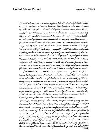
Strength at that end than will support the 450 lbs. but if the short arm is five times shorter than the long one the short arm will have to support 2250 lbs. Thus the four levers with springs or other powers of 450 lbs. to each lever will bear on the ends of their short arms, four tons and a half. The flat springs to be thicker and stronger at the ends which are bolted on. The spiral springs must not be made to draw more 150 lbs each, three of which attached to each lever (one lever at each corner) will bear a weight of 10,300 lbs of the short arms if the levers are one seventh of the whole length. If the loading or weight is 8100 lbs. there will remain a spring power of 2,550 lbs. to act against jolts on the roads. Again the lever with short arm one fifth of its length with a spring to draw 300 lbs. gives 1500 lbs power to each lever, or 6,000 lbs to the four. If then, weight is 3,200 lbs, there remains 1600 lbs. to act against jolts on the roads. Or a lever with short arm one fourth of the length of the bar spring to draw 200 lbs gives the four levers 2,000 lbs power. Thus the weight 1600 lbs leaves 800 lbs. It may be necessary to notice for heavy loading the manufacturer need not be very fastidious whether he makes the short arm of the lever (more especially if it is a long lever) one fifth or one seventh of the whole length (more or less) as it is proved that a very small movement in the rise and fall when in a continued springing motion will cause both the baggage and wagon from the solid force of jolts on the roads to support the shocks of which the manufacturer is necessitated to build carriages very ponderous when without springs.
The props, levers, springs, shackles &c. may be made of any suitable material, but it is proper where the value of the carriage will afford it, to make the springs (particularly the spiral which are considered to be advantageous) of good English sheet steel manufactured by the best workmen in that art. The levers and springs may be made of figured or other ornamental castings either in brass or other varieties of beautiful mixed metals where ornament and but little strength are required... P. S. four steel springs of three pounds weight each, and twenty inches long, two broad at the bolt
Page 12.
United States Patent
Patent No.: X9168
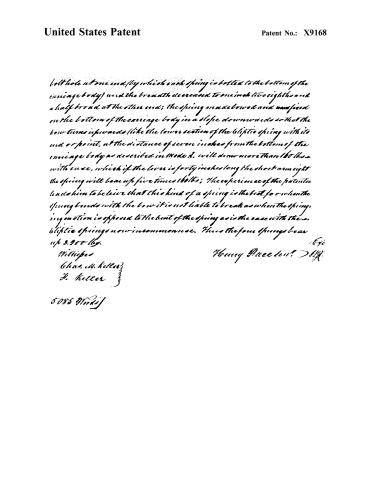
bolt hole at one end (by which each spring is bolted to the bottom of the carriage body) and the breadth decreased to one inch two eighths and a half broad at the other end; the spring is made bowed and fixed on the bottom of the carriage body in a slope downwards so that the lower turns upwards (like the lower section of the elliptic spring with its end or point, at the distance of seven inches from the bottom of the carriage body as described in Model A. will draw more than 16 lbs. with ease, which if the lever is forty inches long the short arm eight the spring will bear up five times 16 lbs.; the experience of the patentee leads him to believe that this kind of a spring is the best, for when the spring bends with the bow it is not liable to break as when the spring in motion is opposed to the bent of the spring as is the case with the elliptic springs now in common use. Thus the four springs bear up 3.200 lbs.
Witnesses
Chas. M. Keller
H. Keller
Henry Dace den. D.M.
5085 Wm. J.
Published accounts: journal notice
Notice in the monthly list of patents, with remarks
Journal of the Franklin Institute, new ser., vol. 17 (1836), p. 333 · View the page
32. For improvements in Hanging Carriage Bodies; Henry Pace, Senr., Cincinnati, Hamilton county, Ohio, October 14.
Remarks. Various modes are described of carrying into effect the proposed plan, of hanging the bodies of carriages, the description of them being given at great length, the following constitutes the claim. "First. To attach as many props and levers, of the denomination of the lever of the first kind,' as may be required for the use of any vehicle, or carriage, drawn or propelled by animal, steam, or other power. One prop for each lever may be fixed on any part of the running gear of the carriage that may suit its use or form, the lever to work free; the fulcrum to be placed at any part of the lever between the weight and the power, at the option of the builder.
About this record
- Patentee
- DATAMP
- Date
- the Name and Date index of patents, DATAMP, USPTO records
- Invention
- DATAMP
- Listed in
- the Name and Date index of patents, DATAMP, USPTO records, Jim Shaw's X-patent list, the Journal of the Franklin Institute, Burke's List of Patents (1847)
- Burke's 1847 Patent Office list gives the same patent.