

Drawings and documents
National Archives restored drawings: drawing
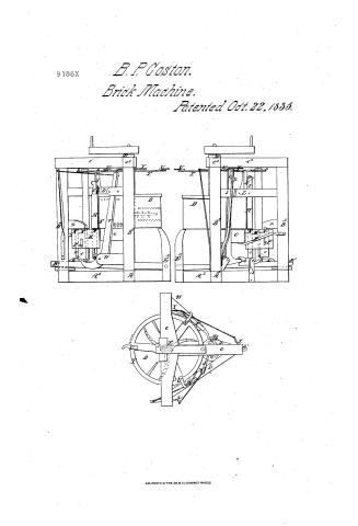
B.P. Coston's Patent Drawing for a Machine for Making Bricks and Tiles

National Archives, Restored Patent Drawings (Record Group 241) · Full-size scan at the National Archives · Catalog record
Show the text on the drawing Hide (67 words)
Words on the drawing as machine-read by the National Archives; not checked. Useful mainly for searching.
Fottp / 27. Clay & Pottery, / Motd-Mayabie, / Michines, / Rotary Disk. Moids in face, / Pien Box Moldi Movabie, / by / are / mb Rotary Disk. Moids in face, / IB3 IID / B. of teston . / 1200 / Machinijor makito Brickettes / CLASSIFICATION / Pritented 22" Dets 1835 / 9186-4 / DIVISION. / all Clay / Stressand Deta / B' unnights from a / c Arms attan / Fi. short unlight
USPTO scan
The patent as scanned by the USPTO
-
 Page 1
-
 Page 2
-
 Page 3
-
 Page 4
-
 Page 5
-
 Page 6


U.S. Patent and Trademark Office · Google Patents
Show the transcription Hide (2,038 words)
Machine transcription (LightOnOCR) of the pages as scanned by the USPTO, most of them the handwritten copies made when the records were restored after the 1836 fire. Not checked; it can misread handwriting, so compare it with the scan.
Page 1.
9186X
B. P. Coston,
Brick Machine.
Patented Oct. 22, 1835.

AM. PHOTO-LITHO. CO. N.Y. (OSBORNE'S PROCESS)
Page 2.
Oct. 22, 1835 9186X 81
Beuton & Boston of Sterling, County of Wayne, Penn.
The Schedule referred to in these Letters Patent, and making part of the same, containing a description in the words of the said Beuton & Boston himself of his improvement in the machine for making Bricks & Tiles.
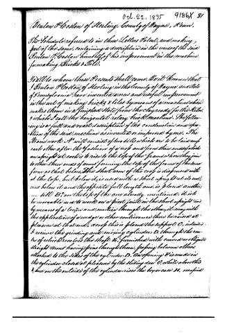
To all to whom these Presents shall come, Be it known that I Beuton & Boston of Sterling in the County of Wayne and State of Pennsylvania have invented a new and useful improvement in the art of making bricks & tiles by means of a machine which makes them in a finished state from the clay ready for the kiln, & which I call the horizontal rotary brick machine. The following is a full and exact description of the construction and operation of the said machine as invented or improved by me. The framework A will consist of two sills which are to be laid one upon each other after the fashion of a roof and from three ends of which an upright at each is to rise to the top of the frame where they join to other three ends of arms forming the top of the frame of the same form as that below. The short arm of the roof is dispensed with at the top, but below it, is used with a short upright at its end, and below it and the opposite full length one, is placed another, ... sill B, on the top of the one already mentioned, it is to be movable and to work on a pivot joint in the short upright and by means of a tenon and mortice through the other, it may with the application of a wedge or other contrivance there be raised at pleasure at that end, across this is placed the support C, intended to receive the grinding and mixing cylinder D, through the centre of which revolves the shaft E, furnished with curved or oblique straight arms having pins through them, passing between others attached to the sides of the cylinder D. An opening F is made in the cylinder closed at pleasure by the sliding door G, while above this & and on the outside of the cylinder rises the box or case H, occupied
Page 3.
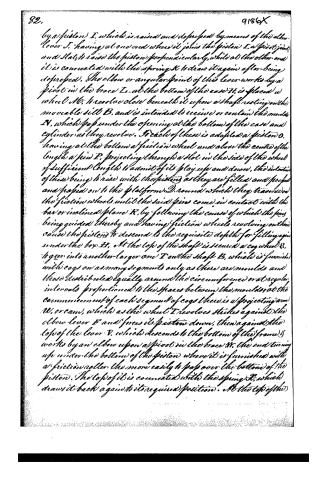
by a piston I, which is raised and depressed by means of the elbow lever J, having at one end where it joins the piston I, a pivot joint, and flat to raise the piston perpendicularly, while at the other end it is connected with the spring K to draw it again after being depressed. The elbow or angular point of this lever works by a pivot in the brace L, at the bottom of the case. It is placed a wheel M, to revolve close beneath it upon a shaft resting on the movable sill B, and is intended to receive or contain the moulds N, which pass under the opening at the bottom of the case and cylinder as they revolve. To each of these is adapted a piston O, having at the bottom a friction wheel and above the centre of the length a pin P, projecting through a slot in the side of the wheel of sufficient length to admit of its play up and down, the intention of these being to rise with the pistons as they are filled and pressed and passed on to the platform D, round which they traverse on the friction wheels until the said pins come in contact with the bar or inclined plane R, by following the course of which the pins being guided thereby and having friction wheels revolving on them cause the pistons to descend to the requisite depths for filling again under the box H. At the top of the shaft is secured a cog wheel S, to gear into another larger one T on the shaft E, which is furnished with cogs on as many segments only as there are moulds and those distributed equally around the circumference or at regular intervals proportioned to the spaces between the moulds; at the commencement of each segment of cogs there is a projecting arm U, or cam, which as the wheel T revolves strikes against the elbow lever F and forces its piston down, then against the top of the lever V, which descends to the bottom of the frame, works by an elbow upon a pivot in the brace W, the end turning up under the bottom of the piston where it is furnished with a friction roller the more easily to pass over the bottom of the piston. The top of it is connected with the spring X, which draws it back again to its required position. At the top of the
Page 4.
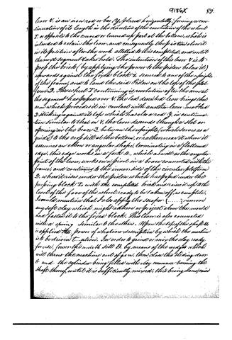
Lever V. is an iron rod or bar, Y, placed horizontally, forming a continuation of its length in the direction of the revolution of the wheel T, or opposite to the curved or turned up part at the bottom, which is intended to retain the lever, and consequently the piston above it in its position after the work allotted to it is completed, and until the next segment takes hold. The intention of this lever V is to press the brick (by applying the power to the piston below it) upwards against the fixed block Z secured to one of the uprights of the frame, and to land the said piston on the top of the platform D. The wheel T continuing its revolution after the arm at the segment has passed over V, the last described lever brings that arm which precedes it in contact with another lever marked D striking against its top which has also a rod Y, in continuation similar to that on V, the lever descends through a slot or opening in the brace B, between the uprights (which serves as a guide) to the crook sill at the bottom, or rather, near it where it assumes an elbow or angular shape, terminating in a flattened edge, this edge works in a fork H, which as well as the angular point of the lever, works on a pivot in a brace connected with the frame, and continues to the inner side of the circular platform D, where it rises under the piston which has passed under the pressing block Z, with the completed brick and raises it up to the level of the face of the wheel ready to be taken off, as complete.
I would mention that I also apply the scraper [......] remove any soft clay which might adhere or project above the mould and fasten it to the fixed block. This lever is also connected with a spring similar to the others. Upon the top of the shaft it is applied the power of whatever description by which the machine is to be driven to action. In order to grind or mix the clay ready for use, lower the movable sill B, by means of the wedges which will throw the machine out of gear, then close the sliding door C and the cylinder being filled with clay commence turning the shaft thereof until it is sufficiently mixed, this being done raise
Page 5.
the side B, and round the wheel Mo until one of the moulds will be brought under the box H, and raise the sliding door G, and start the machine revolutions of the arms in the cylinder D force the clay on, owing to their curved shape a strip slightly into the box H by the opening E and one of the arms W lying against the top of the lever J drives the Piston S fills the mould arm gears into the wheel S, which causes the shaft and wheel Mob revolve towards the pressing block, until it stops under it (from the termination of the cogs in the segment) The arm W has by this time arrived at the top of the lever V, against which it strikes and urges on which produces at the other or curved end, the upright motion under the piston for the purpose of pressing the brick against the pressing block Z, and it is retained in this position by means of the rod or bar Y, until the following segment takes hold on the wheel S when it moves on again, and by the assistance of the lever V, lands the piston O, on the circular platform D, and moves on the brick pressed under the block and scraper 5, which finishes it. By means of the termination of the cogs in the segment the wheel S remains stationary here until one of the arms, M, passing over the top of the lever D, drives it on in the course of its revolution so as to lower the end working in the fork L, which working on its pivot, raises the other extending under the piston which supports the finished brick and raises it up level with the top of the wheel ready to be removed. One of the arms M, has now arrived with its segment again at the lever T, for operated on, & the segment cogs by means of the wheel S, set the wheel M, on the shaft in motion again, which carries on the empty piston and mould towards the box to be filled anew: but in doing this the pins and friction rollers P are obliged to pass under and round the fixed inclined plane or rod R which carries down the piston so as to leave the mould ready to be filled.
Page 6.
At this point the operation is renewed and repeated by the continuance of the power. At the different points of friction where I may deem it necessary, I propose adding friction rollers for reasons which must be apparent. I also form the bottom of the piston, I, with a convex projection for the purpose of filling the moulds in the corners.
What I claim as my invention and not heretofore known or used in my above described improvement for making bricks, and for which I ask Letters Patent is. 1st The manner of forcing the mixed clay into the revolving moulds by the combined action of the lever, piston, and spring constructed and acting on the principles above set forth. 2nd The application of a wheel containing arms or cams and segments only, of cogs upon its circumference at such intervals as to produce the revolution of the moulds at such times as may be required by the arrangement of the levers. 3rd also the pressing the brick against a fixed block by means by means of said and a lever operating and operated on as shown above. 4th The manner of delivering the finished brick from the revolving moulds by means of a lever operating and operated on as described. 5th The manner of opening the moulds by means of the pin & inclined plane or bar, constructed and acting as above. 6th The general construction and arrangement of the several parts of my machine, from which it derives its character; enabling a competent machinist to distinguish it from others invented for moving, moulding, pressing & delivering bricks. But be it understood that I lay no claim to any of these parts individually or separately as they may form elements of other machines, but only the combination and construction of them according to the plan and principles I have above set forth. . . . In testimony that the above is a full and exact description of the construction and mode of operation of my machine as invented or improved by me, I have hereunto set my hand this sixteenth day of September in the year Eighteen hundred and thirty five.
Witnesses:
C. H. Wharton
Henry Stone
(1835)
(Drawing) (Patented 20th Oct 1835.)
Benton B. Boston
Expt. Mgr.
Published accounts: journal notice
Notice in the monthly list of patents, with remarks
Journal of the Franklin Institute, new ser., vol. 17 (1836), p. 340 · View the page
58. For an improvement in the Art of making Bricks and Tiles; Benton P. Coston, Sterling, Wayne county, Pennsylvania, October 22.
Remarks. This patent is not obtained, as the title indicates, for an improvement in the art of making bricks and tiles, but is for a machine for mixing, moulding, pressing and delivering bricks. The description, like the machine, is rather complex; the drawing is referred to throughout; a number of individual claims are made; and to these is added a claim to the general arrangement and combination. A copy of those claims would not be understood without the drawings, it would show, however, that they are not very limited in their character.
About this record
- Patentee
- the Journal of the Franklin Institute, Journal
- Date
- the Name and Date index of patents, USPTO records, Jim Shaw's X-patent list
- Invention
- the Name and Date index of patents
- Listed in
- the Name and Date index of patents, USPTO records, Jim Shaw's X-patent list, the Journal of the Franklin Institute
- The patentee's full name comes from the Franklin Institute's journal.