

Drawings and documents
USPTO scan
The patent as scanned by the USPTO
-
 Page 1
-
 Page 2
-
 Page 3
-
 Page 4


U.S. Patent and Trademark Office · Google Patents
Show the transcription Hide (965 words)
Machine transcription (LightOnOCR) of the pages as scanned by the USPTO, most of them the handwritten copies made when the records were restored after the 1836 fire. Not checked; it can misread handwriting, so compare it with the scan.
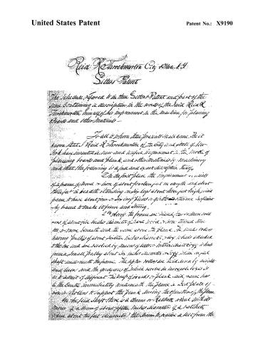
Page 2.
United States Patent
Patent No.: X9190
Reid R. Throckmorton City, N.Y.
Letters Patent
The invention referred to in this Letters Patent and part of the same containing a description in the name of the said Reid R. Throckmorton himself of his improvement in the machine for planing boards and other materials—
To all to whom these presents shall come, Be it known that I Reid R. Throckmorton of the City and State of New York have invented a new and useful improvement in the mode of planing boards and plank and other materials by machinery and that the following is a full and exact description thereof.
On the first place the improvement consists of a frame of wood or iron of about fourteen feet in length and about three feet in breadth standing on legs about three feet high, said frame to have about four or six cross pieces or girdles to sustain sufficient to make it firm and strong.
24 strips to frame are placed two or more rows of about five inches diameter of wood or iron, which are turned into the frame beneath and the same above the plane. The middle rollers having pulleys of about twelve inches diameter, and which are attached to the one end are revolved by means of belts or intermediate cogs which frame a small pulley about six inches diameter, and by means of a shaft underneath the frame. The upper rollers are held down by weights and levers and the grooves of which serve in invariable ways so as to admit of different thickness of boards or plank and same has in the centre immediately underneath the plane a bed plate of iron or steel to support the plank during the operation of the plane.
In the feed shaft there is a drum or Ratchet wheel which is driven by a drum of about fifteen inches diameter of a ratchet wheel about two feet diameter, the drum to receive a belt from the
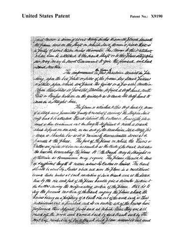
Page 3.
United States Patent
Patent No.: X9190
Just under a drum of about thirty inches diameter placed beneath the frame and on the shaft on which said drum is fixed there is a pulley of about twelve inches diameter. The drum to the ratchet wheel can be attached to the crank shaft or to the plane stay which ever way may be most convenient to give the forward and back — and motion.
The improvement in this machine consists in placing upon the bed plate or sides of the frame six or more pillars or posts upon which are placed the guides or a parallel motion upon these pillars or parallel motion is fixed a crop head with Gill or knives to slide on the guides so as to cause the crop head to move in a straight line.
The plane is attached to this crop head by means of a strap and a permitted party it revolved if desired the strap on said crop head to be attached thereto behind the cutter or front of the plane and is then continued out the length sufficient to reach a crank which is fixed on an axle on one end of the machine. Said strap, pin — man or shackle bar as it is variously denominated serves as a handle to the plane. The part of the plane on which the knives or cutters are fixed is circular as much so as the circle of the crank will allow the handle connecting the plane to the crank may be straight or otherwise as convenience may require. The plane should be made of sufficient length to receive about six cutters or knives. The crank should be about six inches which will move the plane in a rectilinear course twelve inches at each revolution of said crank and at the same time by the rise and fall of the plane handle give a circular motion to the cutters during the reciprocating motion of the plane. That is to say the forward motion of the crank urging the plane ahead, the knives being on a periphery of a circle rise out of the wood each at their individual cut is finished and do so until all of the knives have performed their separate parts and at which time they are all raised off the wood and carried back by said crank and by the next half revolution of said crank said plane moves in out and
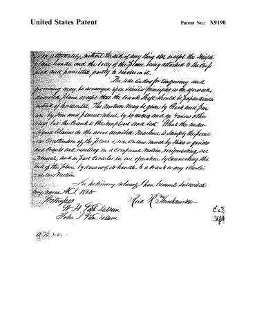
Page 4.
United States Patent
Patent No.: X9190
It is extremely, without the aid of any thing else except the simple plane handle and the body of the plane being attached to the top, had and permitted partly to revolve in it.
The side cutter for tonguing and grooving may be arranged upon similar principles as the above described plane except that the crank shaft should be perpendicular instead of horizontal. The motion may be given by Rack and Pinion by Sun and planet wheel, by levers and in various other ways. But the Crank is the simplest and best. What the inventor claims in the above described machine is simply the peculiar construction of the plane & side cutters moved by the crank and crank and, resulting in a compound motion reciprocating, vertical, and in part circular in one operation by connecting the end of the plane by means of its handle, to a crank or any other circular motion.
In testimony whereof, I have hereunto subscribed my name A.D. 1835
Witnesses
W. H. Tare Salomon
John J. Tare Salomon
Reid R. Shuckminton
956 no. 1
Published accounts: journal notice
Notice in the monthly list of patents, with remarks
Journal of the Franklin Institute, new ser., vol. 17 (1836), p. 340 · View the page
57. For a Planing Machine; Reid R. Throckmorton, city of New York, October 22.
Remarks. This planing machine is very much like that patented by the same person, on the 6th of October, see No. 4. A segment of a circle is to be suspended above the platform on which the board to be planed lies; from the face of the segment project four knives or cutters, the plank resting upon an iron bed, and being carried forward between rollers. The pendulous segment is to be made to vibrate backwards and forwards by a crank, and shackle bar. The claim is to "the peculiar construction of the plane and side cutters, moved by slides or guides and cranks, and resulting in a combined motion, reciprocating, rectilinear, and partly circular, in one operation, by connecting the end of the plane; by means of its handle, to a crank, or any other circular motion." The side cutters mentioned are, as in the former patent, for jointing, tongueing and grooving, and are to act like the upper segment. The remarks which we made upon the former patent, we should be disposed to reiterate, with the exception of acknowledging a little more clearness in the details, in the new specification. The present ought to have been taken for an improvement on the former: as it is, the two are essentially for the same thing, and both cannot stand.
About this record
- Patentee
- the Journal of the Franklin Institute, Journal
- Date
- the Name and Date index of patents, USPTO records, Jim Shaw's X-patent list
- Invention
- the Name and Date index of patents
- Listed in
- the Name and Date index of patents, USPTO records, Jim Shaw's X-patent list, the Journal of the Franklin Institute, Burke's List of Patents (1847)
- The patentee's full name comes from the Franklin Institute's journal.
- Burke's 1847 Patent Office list gives the same patent.