

Drawings and documents
National Archives restored drawings: drawing
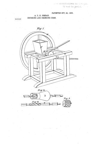
Anderson P.H. Jordan's Patent Drawing for a Machine for Crushing and Grinding Corn

National Archives, Restored Patent Drawings (Record Group 241) · Full-size scan at the National Archives · Catalog record
Show the text on the drawing Hide (94 words)
Words on the drawing as machine-read by the National Archives; not checked. Useful mainly for searching.
of / classigication / 83. MILLS. / 9209+ / Grinding Mills. / Cone and Shell. / DIVISION. / Bet Dela. / comethic / 9209X / Anderson If Jerdan / Crushing g grinding born. / Catented Oct. 28. 1835. / Vol.22.ps. 2021 / Adi / St / References. / a the nut. if. shell .C bar / d. balance wheel l from of happer / sig 1. perspection view.,the hut a theel Tig.o har / sty. 4. nut. / Enlan office April igth ir45. / Made unter the direction of the Commissioner of latent / in conformity with act of 3? march 1834 / Neman Eumorth / Communication of Carent
USPTO scan
The patent as scanned by the USPTO
-
 Page 1
-
 Page 2
-
 Page 3
-
 Page 4


U.S. Patent and Trademark Office · Google Patents
Show the transcription Hide (1,103 words)
Machine transcription (LightOnOCR) of the pages as scanned by the USPTO, most of them the handwritten copies made when the records were restored after the 1836 fire. Not checked; it can misread handwriting, so compare it with the scan.
Page 1.
9209X
A. P. H. JORDAN.
CRUSHING AND GRINDING CORN.
PATENTED OCT. 28, 1835.
The specification on this page is not in print.
Fig. 1.
Fig. 2.
Fig. 3.
Fig. 4.
Page 2.
Oct. 28, 1835 9:20 A.M.
Anderson & A. Jordan, Madison, Tenn.
Letters Patent
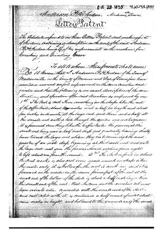
The Schedule referred to in these Letters Patent and making part of the same containing a description in the words of the said Anderson & A. Jordan himself of his improvement in the machine for crushing and grinding Corn
To all to whom these presents shall come
Be it known that I Anderson & A. Jordan of the Town of Madisonville in the County of Monroe and State of Tennessee have invented a new and useful improvement in the corn crusher and grinder and that the following is an exact description of the construction and operation of the said machine as improved by me
1st The Nut is cast from something in the shape like the nut of the coffee mills about ten inches and a half in length and about five inches in diameter at the large end and three and a half at the small end with a hole through the centre one inch square it is furnished something like the coffee mills. The furrows at the small end being near a half inch deep and gradually becoming shallower towards the large end where they are but two or eight and quarter of an inch deep beginning at the small end and ends the large end near you the furrows should incline from right to left about one fourth round. 2nd The Shell or part in which the nut works is also cast iron made much in shape like the nut only it is hollow for the nut to work in and it is furnished on the inside on the same principle of the nut at the small end of the hollow of the shell is about a half inch larger than the small end of the nut. That the corn and the crusher cab may have room to enter connected with the small end of the shell and cast solid with it, is continued a half round of metal about nine inches in length and hollowed to the same size of the small
Page 3.
end of the shell. This also furnished with straight funnels running the whole length and about half an inch deep, in the flat. The twisted bar works.
3. The bar of wrought iron, four inches of the first end of this bar is one inch square, and this is fixed to the balance wheel. On the next four inches a judgion is formed, the next eight inches of the bar is to be made three inches broad and half an inch thick, twisted from right to left half round. This part of the bar works in the spindle of the wheel. Then four inches of the bar is to be one inch square. On this part the nut is to be confined, being well trimmed to the center. On the next three inches the second judgion is formed, then six inches is to be one inch square. On this part of the bar the wallower is fixed if propelled by Horse or water power if by hand a pin is to be fixed in one arm of the balance wheel to form a crank. On the last two inches of the bar a judgion is formed which enters the back plate and is met by a screw or temper from which makes the machine work finer or coarser.
4. The frame is made as follows. First the sills are about three and a half feet long, four by six inches. The sills are connected by one or two cross pieces about two feet between the sills. In these sills are set four posts, four by five inches two in each sill. The posts are about fifteen inches between the sills and plates and eighteen inches apart. On the top of the posts are two more pieces which may be called plates. These plates are to be four by six inches, one of them being split the broad way forming two pieces three by four, in the center between them an indent is to be formed for the first Judgion on the bar. These last mentioned pieces make one plate. The first judgion working between them and the tenants of two posts passing through both pieces are to be keyed on the top. The plates are connected by two pieces two feet between the tenants, none inches apart. Between the last described pieces the shell is to be firmly fixed so that it cannot move out of its place. This is done by letting the open end of the shell into the split plate about half an inch. The other end is made fast by two pieces of iron with holes in each end one by two inches. Three pieces, about two inches wide are bent in the middle so as to fit the shell, their ends extending across the pieces that support the shell. In each of these pieces of timber is made fast a screw with two taps each. These screws pass through the holes in the clamps, or pieces of iron made to fit the shell with one tap below.
Page 4.
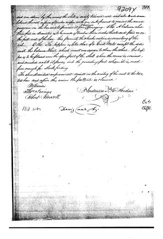
and one above by this means the shell is easily trained nut and also made secure. behind the nut a piece of timber or box with an ink formed to receive the second quagion on the bar and to prevent it from springing - 5th. A balance wheel three feet in diameter is to be made of timber three inches thick and fixed on on the first end of the bar. This prevents the check motion in reversing of the cot. - 6th. The hopper is like that of a Grind Mill except the side must the balance wheel which must one square to clean the wheel. The hopper is to be placed over the open part of the shell where the course is received and crushed until it passes into the grinding part where it is made fine enough for stock feeding.
The above described improvement consists in the uniting of the nut to the two tied bar and upon this union the patent is claimed.
Witnesses
M. P. Grimes
Robert Russell
Anderson & McNeidan
1110 2007
Harris (mar 25)
Ex. 4
ChfW.
About this record
- Patentee
- Jim Shaw's X-patent list
- Date
- the Name and Date index of patents, USPTO records, Jim Shaw's X-patent list
- Invention
- the Name and Date index of patents
- Listed in
- the Name and Date index of patents, USPTO records, Jim Shaw's X-patent list, Burke's List of Patents (1847)
- Burke's 1847 Patent Office list gives the same patent.