

Drawings and documents
National Archives restored drawings: drawing
I.M. McLauglin and H. Hill's Patent Drawing for a Planing Machine

National Archives, Restored Patent Drawings (Record Group 241) · Full-size scan at the National Archives · Catalog record
Show the text on the drawing Hide (247 words)
Words on the drawing as machine-read by the National Archives; not checked. Useful mainly for searching.
#2 - / 144. WOOD WORKING MACHINES / 144, Wood Working Machines, / Planer Feed. / Feed Mechanism / Oct. 1835 / CLASSIFICATION / 92H-X / oblong case. or Box / DIVISION. / b. Division / Planing Machine sumber / 9211 X / a Main axis a portion of which is hollow to the extent of the hollow of the inner Pulley receiving a sticking Rod haveus a projecting / hu halting up through the hollow or exterior cylinder and catching in a nin placedin the hollow of the holley and locking it to the this / by the alternate sliding of the rod from pulley to pulley. secures each pulley in its turn with the exis The reverse motion of the pullies / beins given by one of the Bands being crossed before hassing round the hulley causing a backward and forward motion to the Beuchtop / with the rack undern th and Cog wheel conmetted with the airs / d. Cog wheel c Rack secured to Bench ton I. f. soose pullies havengia hollow space for a min or catch / (g. / Bar let on the shoulder of axis. h cross bar lapping go).i Pivot rod or Aulcrum of rectangular lever formed of sand bass / K. Horizoutal bar. l long lever with knob. m. strange ht and cross bands.n arum o Barand unlights / h. / Plane .D slidies rod / SecoT / grooves / Patent office Oct 31th 1842 / Made under the direction of the comminener nf. / in conformity with act of March 1837 / temmissions of Relects,
USPTO scan
The patent as scanned by the USPTO
-
 Page 1
-
 Page 2
-
 Page 3
-
 Page 4
-
 Page 5


U.S. Patent and Trademark Office · Google Patents
Show the transcription Hide (1,676 words)
Machine transcription (LightOnOCR) of the pages as scanned by the USPTO, most of them the handwritten copies made when the records were restored after the 1836 fire. Not checked; it can misread handwriting, so compare it with the scan.
Page 1.
9211X
McLaughlin & Hill,
Wood Plane Attachment.
Patented Oct. 28, 1835.
AM. PHOTO-LITHO. CO. N.Y. (OSBORNE'S PROCESS)
Page 2.
Oct. 28, 1835
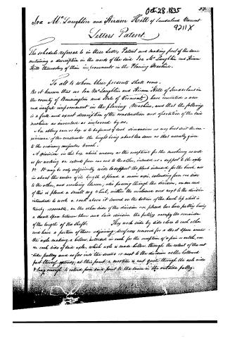
Isa M. Laughlin and Hiram Hill of Sunderland, Vermont-
9211X
Letters Patent.
The schedule referred to in these Letters Patent and making part of the same containing a description in the words of the said Isa M. Laughlin and Hiram Hill themselves of their improvement in the Planing Machine.
To all to whom these presents shall come,
Be it known that we Isa M. Laughlin and Hiram Hill of Sunderland in the county of Bennington and State of Vermont, have invented a new and useful improvement in the planing Machine, and that the following is a full and exact description of the construction and operation of the said machine as invented or improved by us.
a. An oblong case or box is to be formed of such dimensions as may best suit the convenience of the constructor the length being about the same as that usually given to the ordinary carpenter's bench.
b. A division in this box which answers as the reception for the machinery as well as for working, on extends from one end to the other, intended as a support to the axle.
c. It may be only sufficiently wide to support the plank intended for the bench, and in about the centre of its length is placed a main axle, extending from one side to the other, and revolving thereon; also passing through the division, on one end of this is placed a small cog wheel, within the enclosure and next to the division intended to work a rack above it screwed on the bottom of the bench top which is thereby movable. On the other side of the division are placed two loose pulleys leaving a small space between them and said division. The pulleys occupy the remainder of the length of the shaft. They work side by side close to each other and have a portion of their adjoining surfaces removed for a short space around the axle making a hollow, intended in each for the reception of a pin or catch, one on each side of said axle, which axle is made hollow, through the extent of the outside pulley and as far into the second or next to the division as the hollowed part thereof extends; at this point a mortice is cut quite through the axle wide & long enough to extend from said point to the same in the outside pulley.
Page 3.
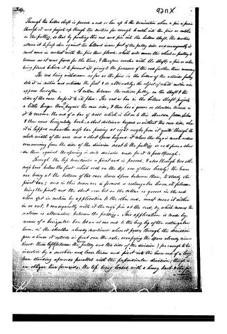
Through the hollow shaft is passed a rod or bar up to the termination where a pin is passed through it and projects up through the mortise far enough to catch into the pins or catches in the pulleys, so that by pushing this rod and pin into the hollow shaft, the mortise allows it to press close against the hollow inner part of the pulley side and consequently it must come in contact with the pins there placed, which will cause the wheel or pulley to become as it were fixed for the time, and therefore revolve with the shaft, a pin or other being placed behind it to prevent its giving to the pressure of the rod further than necessary.
The rod being withdrawn as far as the pins in the hollow of the outside pulley lets it in motion and releases the first and alternately, the object of which motion will appear hereafter. A collar between the outside pulley, on the shaft and the side of the case keeps it to its place. The rod or bar in the hollow shaft projects a little longer than beyond the case side, and then has a groove or shoulder turned in it to receive the end of a bar of wood which is let on to this shoulder from below and then runs horizontally back, a short distance beyond or without the case side, when it is lapped on another cross bar passing at right angles from it quite through the whole width of the case and a short space beyond it where the size is much reduced commencing from the side of the division next to the pulleys so as to form a shoulder there against the opening in said division made for it to pass through.
Through the lap mortises a pivot rod is passed, and also through two other cross bars below the first which rest on the top one of these loosely, the lower one being at the bottom of the case leaves space between them, to steady the pivot bar; and in this manner is formed a rectangular lever, its fulcrum being the pivot and the short arm let on the collar or groove in the rod when set in motion by application to the other end, must move it either in or out, and consequently with it the cross pin at the end, by which means the motion is alternated between the pulleys. This application is made by means of a horizontal bar let on at one end to the long leg of the rectangular lever, at the shoulder already mentioned where it passes through the division from whence it extends in front over the axle, occupying the space already mentioned there left (between the pulley and the side of the division) far enough to be inserted by a mortise and loose tenon and pivot into the lower end of a long lever standing upwards parallel with the perpendicular division, though in an oblique line forwards, the top being loaded with a heavy knot and the fulcrum.
Page 4.
9211X . 95.
furniture consisting of a pivot passing through it & the division & side furthest from the pulleys and beneath the main axle. A moveable pin projecting from the top flank of the bench at the side strikes when in motion against this bar which rests in contact with said side and thrusts it forward, when the knot weight carries it over until it is again struck by the other moveable pin (there being two) when it is sent back again and consequently the motion is communicated by the short-leg to the rod in the hollow shaft, thereby fixing first one pulley and then the other, as it were to the hollow shaft, and causing it to revolve with the pulley in gear. As these pulleys are driven in opposite directions by means of a straight-broad band to one, & a crooked one to the other, running over a drum (revolving in an axle in front of the case set in motion by water or other power) the small cog wheel on the axle must give the same motion by means of the rack to the moveable bench top, this is kept in its position by a groove on its under edge next to the division sliding on two flat fixtures on the top thereof & projecting into the groove, another groove is also formed on the opposite edge to fit on the top of the side pieces, and a perpendicular plank hanging down these sides its. A steel iron at the top and side ends & hook screw or dogs at the other ends to secure the timber. A strong bar is supported by two uprights in a position parallel with the bench & on the side next to the pulleys near the end generally occupied by the workman from this a bar projects over the bench top near close to the upper surface & the position may be changed by numerous holes along it—against this bar the plane is placed in about the position it would be held by the workman & as the revolution of one pulley carries the timber forward, the next pulley brings it back, while the planing continues during that motion; when it changes with the pulley again and so on;
In order to throw the machine out of gear the rectangular lever is so much withdrawn as to leave the pin at the end of the rod or bar in the hollow shaft exactly between the two pulleys and consequently unconnected with either. In this position it is retained by means of a short bar on the side beyond which the long leg projects, having at one end a screw or pivot & at the other a groove or notch to fit on the small end which is thus held securely—we would in some cases fasten the plane by bolts or screws on its side thereby presenting the cutting edge to the side of the timber, which
Page 5.
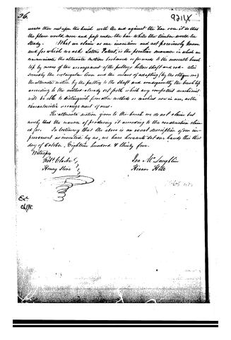
would then rest upon the bench with the end against the bar over it so that the plane would move and pass under the bar while the timber would be steady. What we claim as our invention and not previously known and for which we ask Letters Patent, is the peculiar manner in which we communicate the alternate motion backwards or forwards to the movable bench top by means of the arrangement of the pulleys, hollow shaft and rod. Also secondly the rectangular lever and the means of adapting (by the oblique one) the alternate motion by the pulling to the shaft and consequently the bench top according to the method already set forth which any competent machinist will be able to distinguish from other methods or machines now in use, as the characteristic arrangement of ours.
The alternate motion given to the bench we do not claim but merely that the manner of producing it according to the construction claimed for. In testimony that the above is an exact description of our improvement as invented by us, we have hereunto set our hands this third day of October, Eighteen hundred & thirty five.
Witnesses
Robt. Clarke
Henry Stone
Isa. McLaughlin
Nisam Hite
Published accounts: journal notice
Notice in the monthly list of patents, with remarks
Journal of the Franklin Institute, new ser., vol. 17 (1836), p. 345 · View the page
79. For a Planing Machine; Ira M'Laughlin, and Hiram Hill, Sunderland, Bennington county, Vermont, October 28.
Remarks. We shall not attempt to explain the particular devices adopted by the patentees for giving motion to the different parts of the machinery, (and to which their claims are confined,) as the whole apparatus appears to us to be very interior to several others for the same purpose. The planing is to be effected by a plane of the ordinary construction, and the stuff to be planed, together with the bench on which it lies, are to have a reciprocating motion, the plane being at rest. There, manifestly, must be an enormous waste of power, in thus moving the heavier body backward and forward, instead of the lighter.
About this record
- Patentee
- the Journal of the Franklin Institute, Journal
- Date
- the Name and Date index of patents, USPTO records, Jim Shaw's X-patent list
- Invention
- the Name and Date index of patents
- Listed in
- the Name and Date index of patents, USPTO records, Jim Shaw's X-patent list, the Journal of the Franklin Institute, Burke's List of Patents (1847)
- The patentee's full name comes from the Franklin Institute's journal.
- Burke's 1847 Patent Office list gives the same patent.