

Drawings and documents
National Archives restored drawings: drawing
Joseph Sweet's Patent Drawing for a Machine for Dressing Staves

National Archives, Restored Patent Drawings (Record Group 241) · Full-size scan at the National Archives · Catalog record
Show the text on the drawing Hide (126 words)
Words on the drawing as machine-read by the National Archives; not checked. Useful mainly for searching.
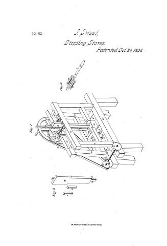
Diezz / 144. WOOD WORKING MACHINES. / Shaving, Fixed Knife. / # 2 / 9215-X / DIVISION: / 9215 / Slaves. / Patented 28 Oct. 1835 / References / Fig 1 Isemetrical view of the machine, wheriam / bouge with its follower k neys is removed / 2 The removed / 3. Regulator or guide / sills. / b brak pieces / Fight / Paste / d. States. / brops-ties. / Fig3. / Kniver or cutters. / h guides. / Keys : to the guides. / R Feollower or drivers. / 1 bail.icon rucks / m Pinion / sarge boy wheel. / small ditte / Balance wheel / Band / r Rulley / is / Circular ruw / Trame of the regulator / u. / Rollers of diths / Handle of ditto / Pinstonest the regulator against / Latent Office. / Made under the direction of the Commissioner of Patents in a / with act 3d March 1837 / MLSunorth / Commitioner of Favents
USPTO scan
The patent as scanned by the USPTO
-
 Page 1
-
 Page 2
-
 Page 3
-
 Page 4


U.S. Patent and Trademark Office · Google Patents
Show the transcription Hide (1,093 words)
Machine transcription (LightOnOCR) of the pages as scanned by the USPTO, most of them the handwritten copies made when the records were restored after the 1836 fire. Not checked; it can misread handwriting, so compare it with the scan.
Page 1.
9215X
J. Sweet,
Dressing Staves.
Patented Oct. 28, 1835.
Fig 1
Fig 2
Fig 3
AM. PHOTO-LITHO. CO. N.Y. (OSBORNE'S PROCESS)
Page 2.
9215X
Oct 28 1835 1.
Joseph Street of Manayun & Pennsylvania
Letters Patent
The Certificate referred to in these Letters Patent and matching front of this issue containing a description in the words of the said Joseph Street himself of his improvement on the machine for Drying Slaves.
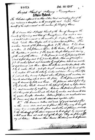
Be it known that Joseph Street of the Town of Manayun in the County of Lehigh and State of Pennsylvania have made a new and useful improvement in the machine for drying Slaves, called Street's Plate Slave Drier which is described as follows: This machine consists of the following parts. 1 The Frame. 2 The House or Culler. 3 The followers or Sliders. 4 The Guides. 5 The gearing. 6 The Regulators or gauges. 7 The Cuvette. 8 The for lifting and lowering of the ends of the Slaves. 1 The frame is made by fastening two sides about 6 feet long and 6 by 7 inches thick. These are placed from 7 to 10 inches apart and connected by cross pieces which are mortised and tenoned into them. Upon the sides are erected four posts about 3 by 4 inches thick, and of a length according to the kind of Slaves to be dried, let into the cells by mortise and tenon, having their tops fitted into long tenons to project above the plates with mortises in them to admit keys which secure the plates to the posts and cells may be secured by bolts and bars. The plates are about 4 feet long 4 by 5 inches thick, secured to the tops of the posts as before described, and connected by cross pieces. Between the posts are framed two short horizontal frames let into the posts by mortise and tenon to bear the guides hereafter described. Tables or platforms are constructed near the houses and slats to rest the slaves and regulators upon.
2. The houses or cullers are made of good cast-steel plate on their inner sides and are so placed that they may be brought near to or receded farther from each other at pleasure, according to the thickness of the slaves required to be dried, by means of a bolt and bar at each end of the houses. They are placed facing at bottom. Between these houses the slaves are to be forced
Page 3.
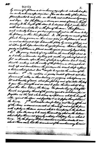
by means of a follower on the iron having cogs upon it, into which a pinion works, as hereinafter described. There are two wells of the knives placed parallel to each other in the still, and well secured by wedges and keys. 3d. The followers or knives are made of wood, in length according to the length of the stone to be dressed 3 by 5 inches thick with cast iron racks let in the face of the stone. These followers work vertically between guides in grooves formed in the stone to keep the followers in their true position. 4. The guides are made of thick plank having grooves on their inner sides for the followers to work in and are secured at top between the plates by means of keys, and at bottom by the before described horizontal frames. Between the two guides and followers is placed another guide secured by keys & bolts. 5. The gearing consists of a cog wheel on the crank shaft about 4 or 5 inches in diameter working into another cog wheel of about 2 feet in diameter upon the axis of which is a pinion 4 or 5 inches diameter working into the racks of the followers or knives, which work up and down between the guides, on the crank shaft is placed a balance wheel of about 300 lbs weight to regulate the motion of the machine. 6. The regulators or guides consist of small cast iron frames with rollers in them turning on gudgeons, which frames are let into handles of wood, about four feet long and of suitable thickness to give them strength and are used to guide the stone whilst being forced thru them between the knives. The operator laying hold of the handle and pressing the end of the guides against a small iron pin or projection in the still which serves as a fulcrum whilst he brings the roller against the stone and regulates it as it passes through between the knives. 7. A circular saw for lising and sawing off the ends of the stones, is secured on an axle at the ends of, and across the frame with a pulley on the same, around which a band passes to the balance wheel; when the saw is to be used, the small cog wheel on the balance wheel shaft is thrown out of gear by a sliding or shifting box in which it turns. In the foregoing I have described a machine similar to one which I have used, but the dimensions of the machine may be varied
Page 4.
9215X
3.
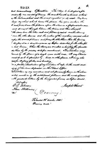
best circumstances. Operation. The Stave to be dressed is placed vertically over a set of knives. The counter-handle is turned, as in the balance wheel and the small cog wheel on its inside. This turns large cog wheel which turns the pinion. This again works up the 6 and forces down the followers, up from the stave on a perpendicular manner and drives it through between the knives and thus shaves it.
The same time the other rack and follower is raised another stave as over the other knives, and the motion of the machine reversed, which raises the second follower and forces the other stave thru the knives, and drives it in a similar manner as before described for the other followers and knives. When the staves are worked, or locating the operator do them by the guides, as before mentioned. This machine may turned by the force of a single man with ease. It may likewise used so as to be operated by horse or other power. It may also used for stripping, spotting and heading.
For a further illustration of my invention I refer to the model and using of the same deposited in the Patent Office.
I claim as my invention and not previously known in the above noted machine is the additional follower and the mode of use, the guide at bottom by the horizontal frames, as before described.
Witnesses
G. J. Gibson
Sam. Hittinius
Joseph Sweet
(Sealing)
Patented 28th October 1855
Drawing made
Published accounts: journal notice
Notice in the monthly list of patents, with remarks
Journal of the Franklin Institute, new ser., vol. 17 (1836), p. 345 · View the page
80. For a Portable Stave Dresser; Joseph Sweet, Murray, Lycoming county, Pennsylvania, October 28.
Remarks. This patent appears to be taken for an improvement upon some other stave machinery, but what other we are not told. The staves are to be forced between knives, by means of followers, which have a toothed rack upon them, and are acted upon by a pinion. The knives are concave and convex, so as to dress each side of the stave, and as one follower rises, another descends, there being two sets of knives, or cutters. The claim made is to "the additional follower, and the mode of securing the guides." The forcing of staves between such knives, by similar means, is not new, nor is it claimed. If there is an existing right to the original machine, the improvement must be used in subservience thereto; we think it probable, however, that it is common property, as such knives have been long used.
About this record
- Patentee
- the Journal of the Franklin Institute, Journal
- Date
- the Name and Date index of patents, USPTO records, Jim Shaw's X-patent list
- Invention
- the Name and Date index of patents
- Listed in
- the Name and Date index of patents, USPTO records, Jim Shaw's X-patent list, the Journal of the Franklin Institute, Burke's List of Patents (1847)
- The patentee's full name comes from the Franklin Institute's journal.
- The residence comes from the Franklin Institute's journal.
- Burke's 1847 Patent Office list gives the same patent.