

Drawings and documents
USPTO scan
The patent as scanned by the USPTO
-
 Page 1
-
 Page 2
-
 Page 3
-
 Page 4


U.S. Patent and Trademark Office · Google Patents
Show the transcription Hide (1,137 words)
Machine transcription (LightOnOCR) of the pages as scanned by the USPTO, most of them the handwritten copies made when the records were restored after the 1836 fire. Not checked; it can misread handwriting, so compare it with the scan.
Page 1.
9220½X
Peters & Dean,
Rotary Pump,
Patented Oct. 31, 1835.
Fig. 2.
Fig. 1.
R. PETERS PHOTO-LITHOGRAPHER, WASHINGTON, D.C.
Page 2.
9220 1/2 X 00.31.1835
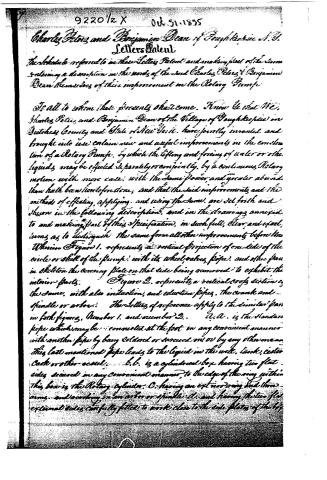
Charles Peters and Benjamin Dean of Poughkeepsie N.Y.
Letters Patent
The Schedule referred to in these Letters Patent and making part of the same
containing a description in the words of the said Charles Peters & Benjamin
Dean themselves of their improvement on the Rotary Pump
To all to whom these presents shall come. Know Ye that We,
Charles Peters and Benjamin Dean of the Village of Poughkeepsie in
Dutchess County and State of New York, have jointly invented and
brought into use certain new and useful improvements in the construction of a Rotary Pump, by which the lifting and forcing of water or other
liquids, may be effected separately or conjointly, by a continuous, Rotary
motion with more ease, with the same power, and greater abundance
than hath been heretofore done, and that the said improvements and the
methods of effecting, applying, and using the same, are set forth and
shown in the following description, and in the drawings annexed
to and making part of this Specification, in such full, clear and exact
terms as to distinguish the same from all other improvements before known.
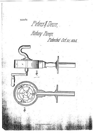
Wherein Figure 1. represents a vertical projection of one side of the
circle or shell of the pump: with its wheel, valves, pipes, and other parts
in skeleton, the covering plate on that side being removed to exhibit the
interior parts. Figure 2. represents a vertical cross section of
the same, with also induction, and eduction pipes, the crank and
spindle or arbor. The Letters of reference apply to the similar parts
in both figures, Number 1. and number 2. A.A. is the standard
pipe which may be connected at the foot in any convenient manner
with another pipe by being soldered or screwed on or by any other means.
This last mentioned pipe leads to the liquid in the well, tank, cistern
Cask or other vessel. B.B. is a cylindrical box having two flat
sides secured in any convenient manner, to the edge of the ring within
this box is the Rotary cylinder C. having an external ring and three
arms, and working on an arbor or spindle D. and having the two flat
external sides, carefully fitted to work close to the side plates of the box
Page 3.
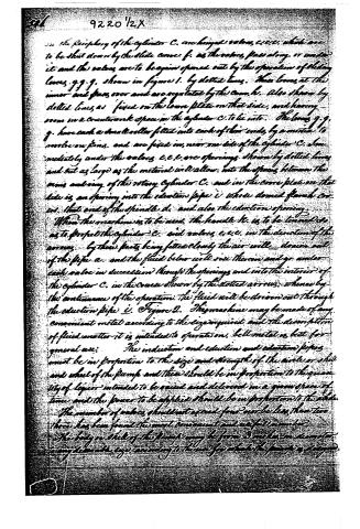
in the periphery of the cylinder C. are hinged valves, c.c.c. which are to be shut down by the slide curve f. as the valves pass along or under it and the valves are to be again opened out by the operation of sliding levers g.g.g. shown in figure 1. by dotted lines. These levers at the inner end pass over and are regulated by the cam h. also shown by dotted lines, as fixed on the lower plate on that side, and having arms in a counterclockwise space in the cylinder C. to lie into. The levers g.g.g. have each a small roller fitted into each of their ends, by a motion to revolve on pins, and are fixed in, near one side of the cylinder C. immediately under the valves c.c.c. are openings, shown by dotted lines and cut as large as the material will allow, into the spaces between the arms and ring of the rotary cylinder C. and in the lower plate on that side is an opening into the eduction pipe i. whose domed flanch covers that end of the spindle d. and also the eduction opening.
When the machine is to be used, the handle h. is to be turned so as to propel the cylinder C. and valves c.c.c. in the direction of the arrows. By these parts being fitted closely the air will draw out of the pipe a. and the fluid below will rise therein and go under each valve in succession through the openings and into the interior of the cylinder C. in the course shown by the dotted arrows, whence by the continuance of the operation, the fluid will be driven out through the eduction pipe i. Figure 2. The machine may be made of any convenient metal according to the size required and the description of fluid matter it is intended to operate on. Bell metal is best for general use.
The induction and eduction and eduction pipes must be in proportion to the size and strength of the circle or shell and wheel of the pump and these should be in proportion to the quantity of liquor intended to be raised and delivered in a given space of time and the power to be applied should be in proportion to the whole. The number of valves should not exceed four nor be less than two. Three has been found the most convenient and useful number.
The body or shell of the pump may be from 3 inches in diameter to any desirable size, according to the use for which the pump is designed.
Page 4.
9220 1/2x
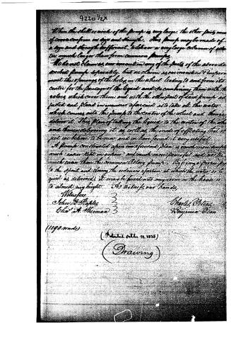
When the shell or wheel of the pump is very large, the other parts must of course conform in size and strength. This pump may be made of a size and strength sufficient to deliver a very large column of water, too much larger than from common pumps.
We do not claim as our invention any of the parts of the above described pump separately, but we claim as our invention & improvement the openings of the holes in the wheel leading to and from its centre for the passage of the liquid and so combining them with the valves which cover them, and with the other parts of said pump adjusted and placed in manner aforesaid as to take all the water which comes into the pump to the centre of the wheel and thence deliver it. This plan of taking the liquid to the centre of the wheel and thence delivering it as well as the mode of effecting that object we believe to be new and we have found it very useful.
A pump constructed upon our aforesaid plan is much more powerful, much easier lifted or drawn, and much more powerful and with the much easier than the common Rotary pump. By fixing a proper pipe to the spout and closing the ordinary aperture at which the water or liquid is delivered, it may be forced into any room in the house or to almost any height. As to our hands.
Witnesses
John J. Staples 3
Chas. A. Sherman 3
Charles Peters
Benjamin Dean
(1190 words)
(Patented Oct. 21, 1855)
(Drawing)
Published accounts: journal notice
Notice in the monthly list of patents, with remarks
Journal of the Franklin Institute, new ser., vol. 17 (1836), p. 347 · View the page
88. For a Rotary Pump; Charles Peters, and Benjamin Deane, Poughkeepsie, Dutchess county, New York, October 31.
Remarks. This rotary pump varies but little in its mode of action from others which have preceded it. There is to be a cylindrical case, with flat heads, and within this a smaller cylinder is to revolve, leaving an annular space between the two for the water chamber. Three valves are hinged, and shut into the inner cylinder, of which, when closed, they make a part of the periphery; they are forced into their places by a stop, or curved plane, which fills the capacity of the chamber in one point. When they pass this, they are forced out by pins, radiating from the centre, and in contact with their under sides; the pins are operated upon by a fixed stationary cam, in the centre of the pump. The water is not to be delivered from an eduction pipe on the periphery of the outer cylinder, as is usually done, but from the centre of one of the heads; to enable it to arrive there, perforations are made through the revolving cylinder, under the valves, this cylinder being hollow, and supported by arms. This latter arrangement makes a prominent part of the claim, and, so far as we know, is new, and, the patentee thinks, very advantageous; we, however, are unable to discover whence its benefits are to be derived. An important thing in every pump is to change the direction of the water as little as possible, and certainly this is not accomplished by the mode of delivery proposed. In other respects, this pump is liable to the general objections to those on the rotary plan, resulting from the accuracy required in their construction, and which, if at first attained, is soon lost by wear.
About this record
- Patentee
- Jim Shaw's X-patent list
- Date
- the Name and Date index of patents, USPTO records, Jim Shaw's X-patent list
- Invention
- the Name and Date index of patents
- Listed in
- the Name and Date index of patents, USPTO records, Jim Shaw's X-patent list, the Journal of the Franklin Institute, Burke's List of Patents (1847)
- The Name and Date index has a note on this number.
- Burke's 1847 Patent Office list gives the same patent.