

Drawings and documents
USPTO scan
The patent as scanned by the USPTO
-
 Page 1
-
 Page 2
-
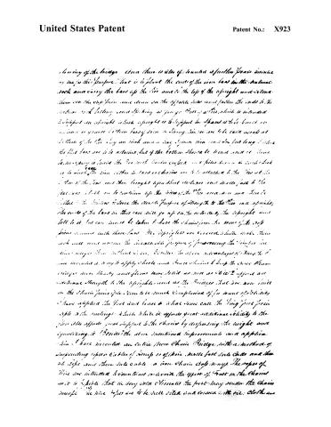 Page 3
-
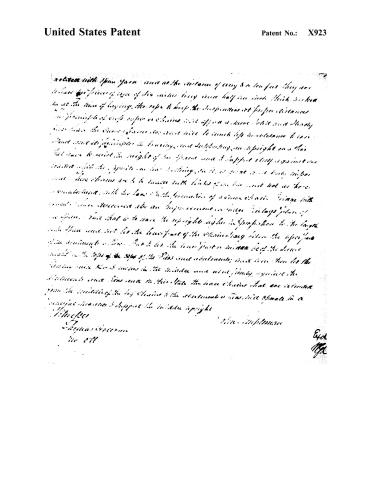 Page 4


U.S. Patent and Trademark Office · Google Patents
Show the transcription Hide (1,261 words)
Machine transcription (LightOnOCR) of the pages as scanned by the USPTO, most of them the handwritten copies made when the records were restored after the 1836 fire. Not checked; it can misread handwriting, so compare it with the scan.
Page 2.
United States Patent
Patent No.: X923
John Templeman
Letters Patent
Issued Aug. 16, 1865.
The subscriber refers to his above Letters Patent and making use of the same containing a description in the body of the said Letters Patent, makes himself of his improvements and applications to his said Suspension Chain Bridge.
Improvement the first. Then the chain is to take for one span for the chains on the uprights that stand on the abutments in the manner as described by the above patent and let them rest in the middle of the curve on the ties with one any upright, hang the chains at first within 12 to 15 inches of the top of the pier, and when the bridge is floored block up to it with square timber tie it takes a proper bearing. Or, as with the Suspension and joints as are written by the above Patent and extend the floor from one abutment to the other, in this case the uprights will require to be higher than in the above "improvement."
Improvement the second. There it may be preferred to use uprights on the pier instead of the foregoing; instead the piers must be constructed in such a way as to have strength enough to support the weight of a load, may be one span while the opposite span has nothing on it. In such cases great strength and proper abutments are indispensably necessary. There a line can be laid in firm natural rock from four to six feet of iron or timber, and such which are to be planted firmly in the natural rock, and at the distance of every four to five feet holes of such square must be made through the flat bars and bars of iron or timber, four feet long are to be run through them in such a manner as to take a strong grip hold of the iron or timber inside of the ties. These flat bars of iron are to extend up and come out at the top of the pier about two feet and then pass through the side of the uprights and then down in such a manner as to bind the uprights to the ties in a more precise way. Where the ties there is to be a hole in the head of the bars of an inch square from which a chain or bar of iron is to be extended up to the head of the top pieces. Besides these precise supports to the uprights there are bars of flat iron to come up the sides of the pier and bolt to the sides of the uprights under the middle of the
Page 3.
United States Patent
Patent No.: X923
lowering of the bridge—then there is also of course a further power necessary by me for this purpose. That is to plant the ends of the iron bars in the natural rock and carry the bars up the side and to the top of the upright and then are the ends from some down on the opposite side and fasten the ends to the natural rock letting some lifting as you go. One of the which is intended to support an upright which is to support the span is to be built on a line or ground bottom long side or string. Lines are to be laid across at bottom of the side by an inch iron a long span iron some six feet long to which the flat bars are to be attached. But if the bottom should be found and it should be necessary to build the two with similar angles and piles driven in each block so that the side either in bars or chains are to be attached to the side at the bottom of the span and then brought up above the surface and made fast to the fasteners which are to continue up the sides of the side and then are filled with the material to serve the double purpose of strength to the side and upright. The ends of the bars in this case will go up on the outside of the upright and bolt to it, but care must be taken to have the chains from the same of the top pieces connect with these bars. My uprights are covered which make them look well and answer the invariable purpose of preserving the timber for time longer than without. I am besides to state advantages of the way I have invented a way to apply these and since chains to keep the more heavy bridges more steady and floors more solid as well as to give it support and additional strength to the uprights, and as the bridges that are now built on the chain principle seem to be much complained of for want of solidity I have applied the fast and loose to what some call the King post principle to the trussings which while it offers great additional stability to the floor also affords great support to the chains by dispersing the weight and equalizing it. Besides the above mentioned improvements and application I have invented an entire New Chain Bridge with a method of suspending ropes or cables of hemp or of iron made fast into chains and then at tops some these into cable or iron chain top ways. The ropes of these are intended to maintain or avoid the effect of frost on the chains so it is possible that in very cold climates the frost may render the chains unsafe. The wire ropes are to be well oiled and covered with oil. Cloth and
Page 4.
United States Patent
Patent No.: X923
relates with Spun yarn and as the distance of every 3 or ten feet they are to have the pieces of rope of six inches long over half an inch thick which to set the time of laying the rope to keep the suspension at proper distances the principle of rope ropes or chains will appear a more solid and steady than have the same forms for rope will be much less troublesome to use and not so complicated in laying and supporting an upright on a flat that there to resist the weight of the Spun yarn to support itself against one another while the Spun yarn has nothing to it, as great as a body upon that these chains are to be made with links of an iron and not as there is constructed with the law of the formation of a chain chain bridge with several chain members also an improvement in bridge bridge plan of suspension that that is to have the upright higher in proportion to the length and then must not let the lower part of the chain long below the upper part that is enough to line but to let the lower part or minor leg of the chain extend to the tops of the tops of the Piers and abutments; and then let the laying over 1000 inches in the middle and about firmly against the abutments and then over in this state the base chains that are connected from the middle of the top chains to the abutments or Piers will operate in a proper manner to support the middle upright
Witnesses
Thomas Brown
No 811
End
1792
About this record
- Patentee
- Jim Shaw's X-patent list
- Date
- the Name and Date index of patents, USPTO records, Jim Shaw's X-patent list
- Invention
- the Name and Date index of patents
- Listed in
- the Name and Date index of patents, USPTO records, Jim Shaw's X-patent list, Burke's List of Patents (1847)
- Burke's 1847 Patent Office list gives the same patent.