

Drawings and documents
National Archives restored drawings: drawing
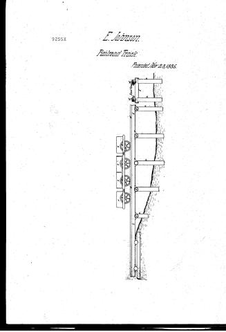
E. Johnson's Patent Drawing for the Construction of Railroads

National Archives, Restored Patent Drawings (Record Group 241) · Full-size scan at the National Archives · Catalog record
Show the text on the drawing Hide (75 words)
Words on the drawing as machine-read by the National Archives; not checked. Useful mainly for searching.
ratlWays. / RAJLWAYS, / Elevated. / 12 Electric / Nol. 23 plage tog / 9255X / DIVISION. / It . o JOHNSON / 9255 X / Palented 23.16021535 / constructuring Ballroads / a. Blocks / sells or sleepen / b. cross Tembers / C. Keys / d. Rails of hard timber / 6-4 / l. Earth Botes / Strechlauds Del / Patent office augton 1842 / Made under the direction of the communines / of / Patent in components with ail of March (m / Communioner of Patents
USPTO scan
The patent as scanned by the USPTO
-
 Page 1
-
 Page 2
-
 Page 3
-
 Page 4
-
 Page 5
-
 Page 6


U.S. Patent and Trademark Office · Google Patents
Show the transcription Hide (1,753 words)
Machine transcription (LightOnOCR) of the pages as scanned by the USPTO, most of them the handwritten copies made when the records were restored after the 1836 fire. Not checked; it can misread handwriting, so compare it with the scan.
Page 1.
E. Johnson.
Railroad Track.
Patented Nov. 23, 1836.
Page 2.
Nov 23, 1835 9255X 109
Elisha Johnson, of Rochester, New York.
Letters Patent.
The schedule referred to in these Letters Patent, & making part of the same containing a description in the words of the said Elisha Johnson himself, of his improvement in the construction of Rail Roads.
Be it known that I Elisha Johnson of the City of Rochester County of Monroe and State of New York, have invented new and useful improvements in the construction of Rail Roads, and that the following is a full and exact description of the materials, machinery, form of construction and the mode of executing the work. First. A timber work of the description represented in Fig 1. prepared and put up in such parts of the line of Rail Road as required embanking a.a.a. blocks of round timber sawed with square ends of any diameter, the most suitable size is 18 inches placed in firm earth by excavating pits or shafts through the roots & vegetable soil and of a proper length to suit the grade line and placed ten feet from centre to centre, in two lines under the line of railing. On these are placed round croptimbers of any size (those of 12 inches diameter and nine feet in length the most suitable) these are spotted and fitted to the blocks, places are prepared in the croptimbers 12 to 15 inches in width over the blocks to receive the sleepers marked in plan b.b.b. - The longitudinal sills or sleepers to be round timber not less than one foot in diameter at the small end, to be well hewed on the upper side squared at the end, and at each ten feet, and the same placed on the croptimbers and secured by keys marked on plan c.c. where the surface is near grade the croptimbers are placed on blocks placed horizontally or laid in tenches in this form all of the line maybe timbered excepting the cuttings. This preparation of timber work is made in timbered land while clearing and slashing the line using any description of timber for blocks and croptimbers and for the sleepers what descriptions for durability in the vicinity.
Drawing marked
Page 3.
110.
vicinity of the line, and sufficiently straight to admit of them being laid surface and to admit the line of track within the flat surface, the roughest description of timber answers for the frame, and is more secure in the grade; where the surface is near the grade line the timber is grubbed and the surface under other parts of the line where there are embankments, to them so are cutt. low, and timber moved off, otherwise the surface is left in its natural state. On the flat surface of the longitudinal timbers are placed rails of hard timber 8 by 4 inches or of any other size temporarily spiked on. On this timber work is placed four six or eight The whole manner of the description used for footpaths, wheeled cars, and the ground as a part of the permanent machinery of the rail road and of the form in common use. The arrangement of the frame and earth boxes are of a new and particular form of construction and adapted to the purpose of completing the excavations and embankments as the work progresses. The cars at short distances are moved by the labourers and greater by horse power. The eight wheeled cars are represented by Fig 23 and have a centre frame and 4 wheels with two boxes 4 by 6 feet and two feet in height hung by hinges or swivels in the centre of the side pieces of the frame and are suspended on the outside of the track and constructed of 1 1/2 and 2 inch plank secured by cleats at the bottom and dovetailed at one end and open at the other and otherwise secured by spikes. At each end of the centre frame is a square frame with one pair of wheels secured to the centre frame, by cleats, staples and keys and when dumped, balances on the axle of the wheels at the pivots and discharges between the rails. The box is secured to the frame between the wheels. The six wheeled cars have but one end frame and a small end box hung by hinges to the end piece of the centre frame before described. The four wheeled cars consist only of the centre frame in the form above described and four boxes of 4 by 6 feet and 2 feet in height secured to the side and end pieces by hinges dumping in the side and centre of track, and better adapted to light cuttings and embankments. The cars enter the cutting from one to two hundred feet from the cutting placed upon the line of grade. The box is then removed.
Page 4.
removed and the permanent timber work put down and again pegged as before completing the road and the entire progress. The iron when any part is completed is used for the removal of materials and for the transportation of goods persons or property until the embankments are permanently used and at which time the temporary rails ribbons or beavilling are taken up the timber adjusted if filled at any point the grade particularly prefenced, examined, and new dressed, and the masonry examined or built if temporarily paved over to favor the transportation of the materials by the line of road. New rails are then put down with care, the iron put on with spike passing through the rails into the longitudinal vills or sleepers, and provision made for passing of the water from the centre of the track at the meeting of the rails which are proposed to be three by four and a half or five inches of the most suitable timber that can be obtained. The grade to cover one and a half inches over the sleepers or longitudinal vills thereby covering within the grade the whole line of timber work except a part of the nail on which the iron rests and thereby favouring the durability of the timber work. The advantages proposed in the above plan of road cars and mode of construction and executing the work is the improvement claimed and described as follows.
First. The application of such timber as is near or in the line of road and in its rough form, and of any strength at small expense, ideally. The use of such timber work for the purpose of grading and the removal of other materials for the construction of the road, and of persons and property in such parts of the line as is completed upon wood or iron temporarily put on) while the embankments are perfecting, completing the embankments, and butttings at one third to one half of the expense of any other known modes.
Secondly. Applicable to extending a line of road into, and through swampy districts where ordinary prairies where timber has to be removed, for the road at great distances as well as earth for embankments.
Thirdly. The plan proposes that all the timber work (excepting
Page 5.
the ribbons on which the iron lays beneath, and secured by the grade and protected in its durability and providing for a continuous bearing of the rail on which the iron lies, removing the difficulty incident to wood roads for locomotive power, and heavy teams, accidents to the machinery prevented by coming in contact with soft timbers when thrown from tracks, with many other advantages in detail not necessary to enumerate. Fifthly. A change can be effected in the operation part of constructing a road in the mode proposed; the labor would be controlled and managed by the agent of the company without contractors and the evils incident thereto by employing practicable superintendents (working men) and small parties employed by them in doing the labor and constructing other parts of the work with weekly worklists, the progress of construction being similar to working the road after constructed, and similar agencies and means employed and all of the economy of rail roads in the transportation of property applied in the removal of the great amount of tonnage required in grading and construction of the masonry and wood work. The saving of laborers and nine tenths of the team work, and avoiding the difficulties incident to the increased demand of labor, Team work, &c. Quantities and forage are important to the interests of a company and the progress of internal improvement, and is particularly applicable to new districts of territory in the progress of settlement and where limited investments of capital would be necessary.
In comparing this plan with other modes of construction or in describing other modes to distinguish the mode proposed, first that all known modes of construction contemplate first grading of the line by contracts or days work by the use of carts teams or wheel-barrows and in some cases temporary ways with chains if temporary earth cars passing on the side of earth banks and time given to a line graded to perfect the banks after which commences (and generally the following season) the construction of other parts of a rail road occupying but to three years for the surveying and construction without any use of the road or benefit from the
Page 6.
the yearly investments. Secondly, that in the construction of rail roads a superstructure is formed upon the grade with uprights from three to five feet apart on which rests the rail secured by keys or wedges leaving no support to the rail between the upright timbers. The ends of the upright timbers and rail are being above the grade. This form is the modern common use with variations adopting similar principles and the use of small light timber sawed and in other known manner larger hewed timber for rails has been substituted with more substantial upright timbers. Remark. The Tonawanda Rail Road is commencing at the city of Rochester, State of New York is now constructing on the plain on which I claim my improvement and is under my direction as chief engineer and is the first road known to have been built or building on any similar plane to which references had to my proposed improvement.
William Wallace
Witnessed
William Hitch
Elisha Johnson
Drawing made
1728 Wids
Published accounts: journal notice
Notice in the monthly list of patents
Journal of the Franklin Institute, new ser., vol. 17 (1836), p. 144 · View the page
715. Rail-roads.-E. Johnson, Rochester, New York, 716 Horse shoe machine. Henry Burden, Troy, New York, List of American Patents for December, 1835.
Published accounts: journal notice
Notice in the monthly list of patents, with remarks
Journal of the Franklin Institute, new ser., vol. 17 (1836), p. 411 · View the page
34. For improvements in the Constructing of Rail Roads; Elisha Johnson, Civil Engineer, Rochester, Monroe county, New York, November 23.
Remarks. The patentee of the improvements which are described is, it appears, the Chief Engineer of the Towanda Rail Road, commencing at the city of Rochester, in the state of New York. The object proposed is to save a very large portion of the labour and cost in filling up when there are to be embankments. The whole description, with the accompanying observations occupy considerable space, and all that we can do, at present, is to give a general idea of the mode of procedure. In passing through a well timbered district, where embankments are to be made, a road is constructed by fixing vertical blocks, or posts, of rough timber, squared at the ends; these may be 18 inches in diameter, and be placed ten feet apart, lengthwise of the road; upon them are to be placed round cross timbers, 12 feet in diameter and 9 in length; these, of course, being spotted to fit on to the uprights. Longitudinal pieces of round timber, not less than a foot in diameter, are to be hewn flat at top, and squared at the ends, in lengths of ten feet. Hard string pieces, 2 by 4 inches, are to be spiked on to the longitudinal pieces, and upon them the cars are to run. "The framed earth boxes are of a new and particular form, adapted to the purpose of completing the excavation and embankments; they are to have four, six, or eight wheels. Those with eight wheels have four earth boxes, one at each end, to dump endwise, and two in the middle, to dump at the sides. The embankments are to be made by filling in along this temporary rail road, and it is to be continued in use until there has been a perfect settling of the earth, serving during this period, all the purposes of transportation; after which the permanent rails are to be laid in the usual manner. The claims made are to the application of such rough timber as is at hand, in the way described. The use thereof for the purpose of embanking, and for transportation during the settling of the earth. The extending of the road into and through swamps and prairies; and the covering the whole of the timber with earth, excepting the ribbons on which the iron plates are spiked. A large part of the specification is devoted to a display of the advantages which are to result from the mode of procedure adopted; the means, however, by which results are attained, are the only things patentable. How much of the plan proposed is to be considered as new, is left to the judgment of those informed in the history of the construction of rail roads; we will remark, however, that we do not find any thing set forth in that clear and discriminating manner which is requisite to secure it under a patent.
About this record
- Patentee
- the Journal of the Franklin Institute, Journal
- Date
- the Name and Date index of patents, USPTO records, Jim Shaw's X-patent list
- Invention
- the Name and Date index of patents
- Listed in
- the Name and Date index of patents, USPTO records, Jim Shaw's X-patent list, the Journal of the Franklin Institute, Burke's List of Patents (1847)
- The patentee's full name comes from the Franklin Institute's journal.
- Burke's 1847 Patent Office list gives the same patent.