

Drawings and documents
USPTO scan
The patent as scanned by the USPTO
-
 Page 1
-
 Page 2
-
 Page 3


U.S. Patent and Trademark Office · Google Patents
Show the transcription Hide (653 words)
Machine transcription (LightOnOCR) of the pages as scanned by the USPTO, most of them the handwritten copies made when the records were restored after the 1836 fire. Not checked; it can misread handwriting, so compare it with the scan.
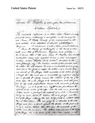
Page 2.
United States Patent
Patent No.: X9273
James W. Waples of Wilmington, State of Delaware
Letters Patent
The schedule referred to in these Letters Patent and made part of the same containing a description in the words of the said James W. Waples himself of his improvement in the spark catcher to be attached to the pipe of a steam engine.
To all persons to whom these presents shall come:
James W. Waples of Wilmington in the County of New Castle and State of Delaware, Engineer duly qualified —
Be it known that I the said James W. Waples, have invented constructed made and applied to use a new and useful machine called “Waples Spark Catcher” specified in the words following viz: The machine consists of two principle parts the catcher A, and receiver B, and is constructed of wire gauge sheet iron or tin zinc or copper the catcher is of a circular form and consists of two flanges C & D connected at the bottom forming a trough E; the inner one is connected by cross bars playing upon a spindle F closely around the exterior of the top of the smoke pipe G. The flanges to be distant from each other from four to six inches proportional however to the diameter of the pipe. The flanges are to be of the same height until from the point H, opposite to the centre of the pipe when the outer one is gradually to taper down in front of to the eighth of an inch or thereabouts leaving an open space I between the wire gauge and that part of the flange allowing the air to pass freely in without obstruction, at that place. The wire gauge K is attached to the outer flanges and from a point opposite the spindle to the front is to be of a coarser texture than that upon the remainder of the catcher and the receiver. The bottom sides and end to the larger of the flanges are to be made of tin, sheet iron, copper or other
Page 3.
United States Patent
Patent No.: X9273
suitable material. The bottom of the machine to be tapered off gradually until the diameter of the end is about one third of the greatest diameter of the catcher. The height of the end to be about two thirds of the greatest height of the catcher which is to be about equal to the lateral distance away opposite the ends of the smoke pipe. The receiver is attached to the catcher by a hinge I at the top. The operation of the machine is as follows: The machine itself being like a scoop, will always present its front to the wind. Sparks rising from the smoke pipe and the wire gauge being distant from the upward draft they fall into the space between the flange and the air blowing briskly through the small opening in front, and through the coarse gauge transfer or carries them at once into the receiver, which retains them until they condense themselves. The whole machine is covered with wire gauge. The cleaning the receiver is effected by a lever lever, M, attached to a hinge N to the bottom of the catcher immediately under the hinge of the receiver. The lever being so arranged that when the end is drawn toward by a cord or wire O, it throws up the receiver and the sparks, ashes, etc., then fall out.
What I claim as my invention, and which I desire to secure by letters Patent, is the before described spark catcher and receiver and the mode of cleaning the receiver.
Witnesses:
Wm. J. Elliot
James M. Waples
(Seal)
(Seal)
648/1
Published accounts: journal notice
Notice in the monthly list of patents, with remarks
Journal of the Franklin Institute, new ser., vol. 17 (1836), p. 416 · View the page
51. For a Spark Catcher; James W. Waples, Wilmington, New Castle county, Delaware, November 30.
Remarks. This spark catcher is to turn, like a vane, at the top of the chimney, a shaft passing up from the centre to sustain, and allow it to revolve. The part immediately over the chimney is covered with wire gauze, forming a segment of a hollow globe, but the whole is extended out on one side, so that the bottom of the spark catcher may be in the form of a long oval, the extended part being called the receiver; the covering of wire gauze is common to the whole, but that part in front, or rather to windward, is coarser than usual, to admit air the more freely, the other end, or receiver, acting as a vane, and keeping the whole in the proper direction. The two parts are united by a hinge at top, allowing the receiver to be turned up, to discharge the sparks, ashes, &c., when they have accumulated. The claim is to "the before described spark catcher and receiver, and the mode of cleaning the receiver."
About this record
- Patentee
- DATAMP
- Date
- the Name and Date index of patents, DATAMP, USPTO records
- Invention
- DATAMP
- Listed in
- the Name and Date index of patents, DATAMP, USPTO records, Jim Shaw's X-patent list, the Journal of the Franklin Institute, Burke's List of Patents (1847)
- The Franklin Institute's journal spells the name differently.
- Burke's 1847 Patent Office list gives the same patent.