

Drawings and documents
National Archives restored drawings: drawing
Fredrick Goodell and T.W. Harve's Patent Drawing for a Power Loom for Weaving Stock-Frames

National Archives, Restored Patent Drawings (Record Group 241) · Full-size scan at the National Archives · Catalog record
Show the text on the drawing Hide (74 words)
Words on the drawing as machine-read by the National Archives; not checked. Useful mainly for searching.
$120 / Looms, Halr Cleth. / CLASSINICATION / 9278-4 / poerboomforteaving / DIV / 9278 / Fatenled Dec 2-1535 / Patented 2 "Decem 183c.m / Vol. 23./0.32 / Hair or brattes / woven alternately / with regular weft / Jime / determined earned for wearing by by shullles marthed hair / wheel M on take up / roller shafr. / Mach under the direction of the to / Patient office 25 grt / of Patents in comformity with actz. / Commition
USPTO scan
The patent as scanned by the USPTO
-
 Page 1
-
 Page 2
-
 Page 3
-
 Page 4
-
 Page 5
-
 Page 6


U.S. Patent and Trademark Office · Google Patents
Show the transcription Hide (2,339 words)
Machine transcription (LightOnOCR) of the pages as scanned by the USPTO, most of them the handwritten copies made when the records were restored after the 1836 fire. Not checked; it can misread handwriting, so compare it with the scan.
Page 1.
No Printed Specification Available.
9278X
Goodell & Harvey Loom.
Patented Dec. 2, 1835.
Fig 3
Fig 2.
Fig 1.
Page 2.
9278X Dec 2, 1835 321.
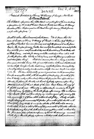
Frederick Goodell (and) Thomas W. Harvey of Ramapo New York
Letters Patent.
The Schedule referred to in their Letters Patent and making part of the same containing a description in the words of the said Frederick Goodell and Thomas W. Harvey themselves of their Improvement in the Power Loom for weaving Stock frames and for other purposes.
To all to whom these presents shall come. Ye it known that We Frederick Goodell and Thomas W. Harvey of Ramapo in the County of Rockland and State of New York have invented a new and useful improvement in the power loom for the purpose of weaving bristles hair or whale bone splints into a web of cotton linen or silk yarn used for mats sticks and the foundation of made Sticks call it Stock frames, and also for weaving such like materials or straw into a web for other purposes than Sticks or Stock frames and the following is a full and exact description thereof. First to a common power loom having a suitable frame yarn and cloth beams take up and stop motion to the reed shuttle crank and cam shafts bars or handles, head cams and picker fixtures having pullies a pair of cog wheels connecting cranks and cam shafts, cam and crank arms which + roller &c. The same substantially as are in general use in the common power Loom for weaving plain cloth with the exception of comprising the width of this Loom to twenty inches or thereabouts between the frames we have suspended an apparatus for placing the Bristles into the web by flocks or pieces a plain being placed on each side of the web beside of the same broad between the range of the shuttle and the reed. Secondly an apparatus for measuring the length of Stock frames by stopping the bristle flocks after weaving 1 3/4 inches (one nlp) Bristle cloth and then starting in motion again after weaving 2 1/2 inches more only.) of plain cloth without bristle filling. Thirdly, an apparatus for changing the movement of the picker from a shot of the shuttle with thread filling every stroke to one in two strokes of the latter while weaving bristle cloth to wit, a shot of thread filling and a shot of bristles alternately but picks every beat of the latter while weaving plain cloth without bristles. For a description of which reference is had to the drawing annexed A. A. Fig 1 Bristle flocks or pieces attached to the latter and move
Page 3.
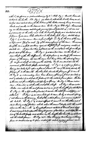
with it (see pinions on sectional drawing Fig 3.) B.B. Fig 1. Bristle boxes attached to the Lathes. F.F. Fig 1. are sides to which the bristle boxes are attached and extend down to the bottom of the lathes, whereby being connected, threads and works on the transverse cam. U.U. Fig 2. D.D. Fig 1. levers working in the transverse and straight grooves (opened by switches a) at one end and connected at the other end with the bristle forks and sustained at the fulcrum by an arm C.C. attached to the lathes. G.G. Fig 1. switch stands.
Fig 1. is a transverse cam on front shaft. L Fig 2. the arc of the cam is depressed 3/4 of an inch 1/4 of the circumference of the cam. The remainder of the cam is full working against the plunger F and gives motion to switch a. A similar cam is placed on the end of said shaft on the opposite side of the loom. H Fig 1. is a similar cam on the back or cam shaft with this difference. The depression is one half the circumference of the cam, its use the same but being twice the speed of cam G. on front shaft it changes the switches two to one and directs the movement of the bristle forks accordingly. L Fig 1. is a spring fastener having two holes to fit upon a pin in stand H. One of the holes directs the plunger F to the cam H. The other hole directs the plunger F to cam G.
K Fig 1. is a connecting lever between plunger F and switches a and is attached to a stand K fastened to the outside frame piece. The loom is thrown out from the framed top by a spring. M. Fig 1. is an index cam. A similar is at the other end of the shaft. N. Fig 1. is an index Roller over which the web passes and is in girt the length of a stock frame. O. Fig 1. is a top roller of metal to secure the cloth from slipping on roller N. P. Fig 1. is an arm held up to cam M by a smart spring (not shown in the drawing back of the outside frame and moves in point at 2, 2, 2. Q Fig 1. is a rod affixed to arm P. on the other end of said Rod is a dog fixture which when the arm P drops in to the indentation in the cam M. is brought forward outside of lever L and drops it and serves to hold open the straight groove of switch a. and stops the motion of the bristle forks and determines the length that bristles are to be worn into the stock frame. R Fig 1 & 2. is a changing cam having a sliding piece so constructed as to open a straight and a zig zag groove and
Page 4.
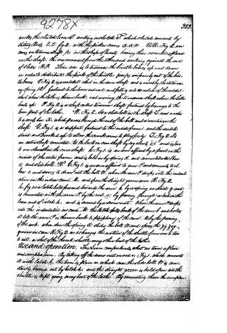
under the clutch lever S. working in the tooth T, which is a tooth connected by sliding rods t, t, fig. 2, with the picker arms a, a, a. U, U, fig. 2, are cams on the main shaft p, in the shape of hearts, having their eccentric planes on the shaft. The one moves from the other and working against the end of slides K, K, their use is to turn the bristle boxes up and down in order to distribute the picks of the bristle pieces uniformly out of the bristle boxes. V, fig. 2, is a toothed wheel on the same shaft and is moved by the stationary spring R, fastened to the lower end seat and falling into the notches of the toothed wheel when the latter is thrown back, and moving the traverse shaft when the latter beats up. O, fig. 2, is a shaft called traverse shaft fastened by bearings to the lower part of the lath. N, fig. 2, is a slide bolt in the shaft S, and reaches to a cross bar X, which passes through the end of the bolt and a screw in the shaft. U, fig. 1, is a support, fastened to the inside frame, and the work stands and is rocked up to allow the crank arms to play freely. O, fig. 2, is an extra shaft connected to the back iron cam shaft by cog wheels V, V, and is two to one slower than the cam shaft. W, fig. 1, is an arm affixed by a pivot on the inside of the outer frame and is held in by spring A, and connected with bar E and slide bolt W. O, fig. 1, is an arm affixed to arm O and connected to slide bar E and serves to draw out the bolt W, when the arm O drops into the indentation in the index cam M, and opens the straight groove arm R, fig. 2. h, fig. 1, is a latch held forward towards the arm b by a spring on stand g, and is connected with the arm O by the rod, r, by passing through a hole in the lower end of latch h, and is secured by a screw nut. When the arm O drops into the indentation in cam M, this latch falls back of the arm b and holds it till the arm O is thrown back to the periphery of the cam M by the passing of the web, when down the spring d slides the bolt W, and opens the zig zag groove in cam R, fig. 2, and changes the motion of the shuttle from one to two to act, a shot of the thread shuttle every other beat of the lath.
Use and operation. This loom comprehends what we term a plain and complex loom. By taking off the screw nut on rod r, fig. 1, which connects it with latch h, the loom is plain in which case the slide bolt W is constantly barred out by latch h, and the straight groove is held open and the shuttle is kept going every beat of the lath. By connecting them the complex
Page 5.
loom is constituted whereby the zig zag groove above described is opened and the shuttle motion is changed from a pick every beat to one every other beat of the lathe. During this space the loom is weaving bristles into the web and threading to a pick every beat of the lathe while the bristle forceps are at rest. The zig zag groove is formed to open 3/4 of the circumference of the cam A. The remainder of the circle is stationary so that this shaft being two to one slower in movement than the back or cam shaft, moves the clutch F Fig. 2, which connects with the three picker cams, X, X, X, by the slide rods LL, in a manner for the cams to miss the picker treadles, alternately first one and then the other. The picker cams are securely affixed to the slide rods LL and slide upon a feather affixed in the cam shaft. The cams marked 1 and 2 have their eccentricities alike and are directly opposite to the one marked 3. The switches a, a, swing on a pivot and when thrown inward open a transverse groove into which the lever D works and throws forwards the forceps. When thrown outward a straight groove is opened and the forceps are at rest. The movement of the switches is indicated by the cams G, G, and H, H, Fig. 1. When the plunger F is set to cam G, the straight groove of the switch is open 3/4 and the transverse groove is open 1/4 of the time. By reversing this cam G to the one on the opposite end of shaft D Fig. 2 a motion will be given to the right and left hand forceps alternately missing one pick of bristles every other beat of the lathe, or if the cams, G are set to agree with each other both forceps pick at the same time at every fourth beat of the lathe. When the plunger F is set to cams H, the same effect is produced in every respect with the exception of doubling the frequency of the picks of the forceps, the cam shaft being two to one in speed of the shaft L, Fig. 2.
Operation of the Bristle forceps — When the lathe is thrown back and the pins are shot through the web into the bristle box, the button u, Fig. 3 strikes a propelling piece and turns the button from its seat against the lower arm of pinion marked v, Fig. 3, when the spring part of the fork marked y, shuts and seizes the bristles when upon the return of the lathe to beat up, the forceps are brought back with the bristles till their bars have reached the opposite edge of the cloth when the lower arm of the forceps rises on to a regulating piece and forces them open when they grasp the bristles.
Page 6.
which are caught by arcing the shade of the web at that instant the forceps being carried still farther back until the button is turned into its seat again by striking against said regulating piece. That part of the forceps marked w. Fig 3. Keys into the slide piece y and serves as a standard for the forceps and protects their points from entangling in the web by projecting beyond the point of the forceps. The slide piece 2 is seated upon the race board of the loom and is connected with lever D. Fig 1. The forceps and the shuttle pass through the web at the same instant and in different ranges from each other in such a manner as not to interfere with each other. Each bristle box is set opposite to its respective forceps a space of two inches being open to receive them the capacity of the boxes being 3/8 of an inch thick and as high as desirable, and as long as the bristles, the bristles are kept down by placing metal weights of the caliber of boxes over them. What we claim as new and distinctly Patent is. First the manner of working the bristle forceps and their connection including their combination with the switches a, a, and frame cams G and H. Secondly the manner of traversing the bristle boxes. Thirdly the manner of changing the motion of the shuttle and its connection with the index cam N. Fourthly the manner of measuring off the length of the cloth frame, by the operation of the loom as combined with the changing motion of the shuttle in claim third and in connection with the index roller and cam with the stop rod Q which dogs the switches. Fifthly the use of two pairs of bristle forceps to a loom a pair on either side of the web, by which the bristles are placed butts and flanks alternately into the web. Sixthly the manner of protecting the points of the bristle forceps by the projecting piece marked w. Fig 3. it being longer and broader than the points of the forceps. And Lastly to the general arrangement of the above claimed parts in its adaptation to a common Power Loom
Witnesses
J.M. Graham
Henry W. Harrens.
Frederick Goddell
Thos. W. Harvey
(Patented 20 Dec 1838)
(Drawing)
Published accounts: journal notice
Notice in the monthly list of patents
Journal of the Franklin Institute, new ser., vol. 17 (1836), p. 144 · View the page
745. Weaving stock frames.-F. Goodell and T. W. Harvey. Ramapo, N. Y.
Published accounts: journal notice
Notice in the monthly list of patents, with remarks
Journal of the Franklin Institute, new ser., vol. 18 (1836), p. 38 · View the page
11. For Weaving Stock Frames; F. Goodelle and Thomas W. Harvey, Ramapo, Dutchess county, New York, December 2.
Remarks. These stock frames are to be woven in a power loom, constructed for the purpose. The apparatus is necessarily complex, and does not admit of verbal description. The patent is accompanied by a very perfect engraved representation of it with numerous references. After describing the apparatus, the patentees make seven distinct claims, to those parts of the apparatus by which the loom is adapted to the special purpose to which it is to be applied. Were we to give these claims they would not afford any correct idea of the particular construction of the things claimed; upon a careful examination of them we do not find any thing which does not appear new in the manner, and for the purpose, to which it is applied.
About this record
- Patentee
- Jim Shaw's X-patent list
- Date
- the Name and Date index of patents, USPTO records, Jim Shaw's X-patent list
- Invention
- the Name and Date index of patents
- Listed in
- the Name and Date index of patents, USPTO records, Jim Shaw's X-patent list, the Journal of the Franklin Institute, Burke's List of Patents (1847)
- The Franklin Institute's journal spells the name differently.
- Burke's 1847 Patent Office list gives the same patent.