

Drawings and documents
National Archives restored drawings: drawing
B. Gill's Patent Drawing for a Cooking Stove


National Archives, Restored Patent Drawings (Record Group 241) · Full-size scan at the National Archives · Catalog record
Show the text on the drawing Hide (50 words)
Words on the drawing as machine-read by the National Archives; not checked. Useful mainly for searching.
Sheet 1. STOVES: / [154] Cooking Stoves. / CUASEI / 92854 / B. CILL / Patented, 9th Dut1835. / COOKING STOVE. / 92% / V, 23.p.333. / SECTION ON THE LINE A.B. / for / let. the topu ar receiver as arranged / FRONT VIEW.
Sheet 2. 9285-X / 9285X / I'
USPTO scan
The patent as scanned by the USPTO
-
 Page 1
-
 Page 2
-
 Page 3
-
 Page 4
-
 Page 5
-
 Page 6
-
 Page 7
-
 Page 8


U.S. Patent and Trademark Office · Google Patents
Show the transcription Hide (2,054 words)
Machine transcription (LightOnOCR) of the pages as scanned by the USPTO, most of them the handwritten copies made when the records were restored after the 1836 fire. Not checked; it can misread handwriting, so compare it with the scan.
Page 1.
9285X
B. GILL.
Cook Stove.
3 Sheet—Sheet 1.
Patented Dec. 9, 1835.
Section on the line A.B.
Y
R
Q
I
F
C
D
Front View.
R
N
N
L
O
M
F
B
C
D
Page 2.
9285X
B. GILL.
Cook Stove.
3 Sheet—Sheet 2.
Patented Dec. 9, 1835.

Page 3.
9285X
B. GILL.
Cook Stove.
3 Sheet--Sheet 3.
Patented Dec. 9, 1835.

Page 4.
Bennington Gill of New York City.
Letters Patent.
The Schedule of annexed to this Letters Patent and making part of this issue containing a description in the words of the said Bennington Gill himself of his improvement in the Cooking Stove.
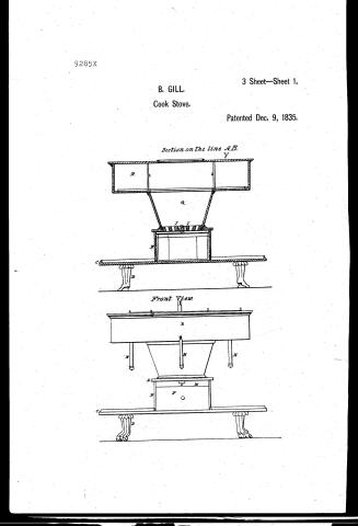
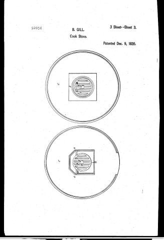
To all to whom these presents shall come, Know Ye that Bennington Gill of the City County and State of New York have invented and constructed and made and applied to use a new and useful improvement in a cooking Stove, called "Gill's improved cook Stove" which improvement and the Stove wherein it is made is described as follows, namely. For the bottom of the Stove I make a circular plate of Iron C (see drawings) two feet six inches in diameter and of suitable thickness, which plate I raise from the ground about five inches by feet D (see drawings) sliding into dovetails on the under side of it. Upon the centre of this plate I place a cast Iron Box E (see drawings) ten inches square closed on three sides and open on one side for the admission of the drawer F (see drawings) to contain the ashes. This drawer is four and one half inches deep and nine and one half inches wide. On the inner surfaces of the right and left sides of this box I cast projections G (see drawings) with hollows upon the upper parts for the admission of the ends of the axle of the revolving and falling grate described below. This Box I sometimes cast permanently with the circular plate forming the bottom of the stove, and sometimes cast separately and confine it to its place by rods passing through its cover and the plate secured by nuts below. Upon the above described projections on the interior sides of the Box, I place the axle H (see drawings) of a circular grate I (see drawings) which axle is fastened to the grate by a pin passing through the centre of the grate and a projecting part K (see drawings) of the axle. This projecting part is two inches in length and the grate is seven and three quarter inches in diameter, and revolves freely round the pin which attaches it to the axle. On the under side of the grate I cast two dovetails each extending from the edge of the centre bar to the next bar on the side of it and back about three inches leaving a triangular slot
Page 5.
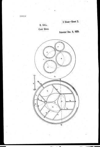
opening between them to receive the shaking pin P. (see drawings.) This pin I make of three eighths inch round steel plate at one end and with a loop on the other. Upon the top of the above described I place the area E which is a plate eleven inches square having a circular aperture in the centre eight inches in diameter (in which the circular grate moves) and having near the front edge a projecting part M (see drawings) on the lower side one inch wide and nine and a half inches long extending down to meet the front of the ash drawer. In this projecting part of the area I make an oblong hole O (see drawings) about three inches long and half an inch wide, through which it passes the shaking pin into the slot between the doortails under the grate with the flattened end in a vertical position in which way it will pass through the slot until the flattened end gets beyond the doortail, when I turn the pin so as to bring the flattened end into a horizontal position where it cannot be drawn out being prevented by the narrowing of the passage between the doortails. Upon this area I place a cylinder Q (see drawings) seven and three quarters inches in diameter at bottom and twelve inches at top and seven inches high. This is the chamber of combustion, holding the fuel and having the circular grate at bottom. Upon the top of this cylinder I place the receiver R (see drawings) which is twenty-four inches in diameter at bottom, twenty-four and three quarters inches at top and five inches inches deep, having a circular aperture in the centre twelve inches in diameter, fitting the top of the cylinder through which the heat and smoke ascend into the receiver. Across this circular aperture and immediately over the cylinder, separating from each other those parts of the boiler holes which extend over the cylinder. I place a partition S (see drawings) made of iron, fire brick, soapstone or other suitable material having flanges on the lower edges to receive the dampers or slides T (see drawings) and having one of its ends forked to facilitate the action of the valve V (see drawings.) These dampers or slides are made to shut over that part of the circular aperture which is under either of the boilers so that by opening the proper valve and closing the others, the whole current of the fire from
Page 6.
The cylinder can be directed in the first instance under a particular boiler, while by the action of the vertical valve described below, the heat and smoke are compelled to pass around the receiver and away over all the other Boilers at will. On the inner side of the bottom receiver are pairs of cast iron guides, U. (see drawings,) about three eighths of an inch high, extending from the points where the partition meets, upon the bottom of the receiver back to the inner side of it so as to regulate the action of the dampers as they are moved backward and forward. In the damper, I affix rods, N. (see drawings,) passing through the rim of the receiver with brass or other balls on the outer ends, about one inch from the union of the rod with the damper. I make a joint in the rod which permits it, when the damper is drawn back, to fall into a pendant position on the outside of the receiver. On one side of the receiver and opposite to the forked end of the partition I make an oval opening, W. (see drawings,) and an oval collar for the attachment of the pipe. On each side of the opening and attached to the inner side of the rim of the receiver are projections, X. (see drawings,) about one inch wide extending from the bottom to the top of the receiver, against which the vertical valve shuts as it is moved in either direction. This valve extends from the partition to the outer edge or rim of the receiver and is made to move in a vertical position in the groove formed at the fork of the partition, so that when it shut against either of the above described projections it shuts out the passage of the heat and smoke from the receiver to the pipe in that direction. On the top of the Receiver, I place I place the cover Y. (see drawings,) a circular plate fitting by a groove or bead to the receiver in which are holes to admit the cooking utensils or fuel, which holes when not occupied by the cooking utensils are covered by girdles, Z. (see drawings,) the vertical valve is moved by a handle attached to a part of it projecting through the cover of the receiver, by which valve the draft can be made to pass round the top of the stove or receiver and Boiler in it from right to left or from left to right at pleasure, or I place a permanent partition across from the side of the receiver to the inner partition and dispense with
Page 7.
336. 9285X
the vertical valve. The stove above described is intended for burning coal. When wood is to be used for fuel the form of the chamber of combustion and lower parts of the stove are altered, but the receiver is the same as above described, and the flame and smoke ascend into it in the same manner through the circular aperture in the bottom. I perform heating & and roasting in all or either of the following ways: 1st By an iron oven in the rear of the chamber of combustion, round which I cause the fire to circulate before it is admitted into the receiver above. 2nd By tin or other reflectors placed under the receiver and in front or at the sides and back or around the chamber of combustion; or. 3d By tin or other irons & reflectors placed upon the top of the receiver. The forms of the Receiver of the Boilers and the Water holes of the position within the receiver and their valves may be varied, but in all cases in such manner that the direct communication between the chamber of combustion and the bottom of each boiler may be shut off at pleasure by valves operating either by sliding horizontally or vertically, or turning upon an axle or in any other mode that the form adopted for the Boiler holes & receiver may render expedient. By which means, as will be seen by reference to the model a great economy of fuel is effected. The heated air in its course to the chimney is so directed as to pass under the bottom of all the Boilers and at the same time effectually to warm the ovens while valves so command the direct heat from the fire that a greater or less portion can be had at pleasure for each or any Boiler without disturbing or deranging the action of the heat upon any other Boiler or upon the oven. A comparison of this model with any stove previously made will show its excellency. The top or receiver may be square or circular as in the model and drafts or angular or an hexagon or an octagon or any other convenient form and may with the other parts of the stove be varied in size to suit the purchaser, taking care to preserve the proportions. The drawings annexed will show more accurately the form of the parts and to them reference is made. The part of the above described stove in which any improvement is made is the top or that part which is above the furnace chamber for
Page 8.
the fuel and which I have called the Stove, and it consists in the new arrangements above described in a stationary top of the stove so as effectually to distribute and guide the heat when generated to those parts or objects for which it is wanted in such proportions & in such times & in such manner as may be required. This is effected by arranging the cooking utensils or vessels over the fire as above described & by providing the horizontal slide, or valve to close in part or whole as may be needed the apertures through which the flame & heat ascend and by means of the perpendicular valve or other fixture at or near the smoke pipe outlet of the top for the purpose of giving direction to the flame and heat and the internal arrangement & construction of the above described parts in and upon the top of the stove, the whole being combined in such a manner as to produce the desired results. I claim as my invention and improvement the construction arrangement and combination of the above described parts comprising the interior of the top of said stove and any the similar arrangement & combination of similar parts for the same purpose placed over the fire in the top of a stove for the purposes aforesaid and for this improvement I request Letters Patent.
Witnesses
J B Staples
James Humphreys
Bunnington Gill.
(Drawing.)
Published accounts: journal notice
Notice in the monthly list of patents
Journal of the Franklin Institute, new ser., vol. 17 (1836), p. 144 · View the page
747. Cooking stove. -Bennington Gill, City of N. Y.
Published accounts: journal notice
Notice in the monthly list of patents, with remarks
Journal of the Franklin Institute, new ser., vol. 18 (1836), p. 38 · View the page
13. For a Cook Stove; Bennington Gill, city of New York, December 9.
Remarks. This stove is intended principally for the purpose of cooking by means of anthracite, but the fire place may be so constructed as to burn wood, if deAmerican Patents for December, with Remarks. sired. The bottom plate is to be circular, to stand on feet, and to sustain a square box for the ash pit drawer. Above this is the fire place, which is made conical, its lower end being about seven inches in diameter, its up per about twelve, and its height about seven. This is surmounted by what is called the receiver, consisting of a circular plate fitting on the upper edge of the fire place, having another five inches above it, forming the two, with their rim, a flat cylinder which receives the lower parts of the cooking utensils through openings in the top plate. A plate within the receiver, over the fire, serves to distribute the heat laterally, and there are sliding valves, or dampers, to direct it under any particular vessel. The claim made is to the arrangement of the respective valves, &c. within the receivers. The difference between this stove and some which have been previously made is not very great, and so far as we can judge from the description and drawings, which are by no means defective, we should much prefer one of Stanley's rotary stoves to it, as being less complex, and more convenient.
About this record
- Patentee
- the Journal of the Franklin Institute, Journal
- Date
- the Name and Date index of patents, USPTO records, Jim Shaw's X-patent list
- Invention
- the Name and Date index of patents
- Listed in
- the Name and Date index of patents, USPTO records, Jim Shaw's X-patent list, the Journal of the Franklin Institute, Burke's List of Patents (1847)
- The patentee's full name comes from the Franklin Institute's journal.
- Burke's 1847 Patent Office list gives the same patent.