

Drawings and documents
National Archives restored drawings: drawing
J. R. Cambell and H.C. Cambell's Patent Drawing for an Improved Lock

National Archives, Restored Patent Drawings (Record Group 241) · Full-size scan at the National Archives · Catalog record
Show the text on the drawing Hide (58 words)
Words on the drawing as machine-read by the National Archives; not checked. Useful mainly for searching.
SLOCKS & LATCHES, / VIK / Lecks, Perm Tatlen- / Retating Tumblers, / CLASSIFICATION / 9294X / Improval Lack. / DIVISION. / 9294 / Patented 28 Decbr.1835. / Figl. / B Balt / the / private / Il. / I- true notches / Fig 2 / Il / A Bolt / IM / OB / A Balt / Pins C parathrough holes B in the bolt / 71 / (fdema
USPTO scan
The patent as scanned by the USPTO
-
 Page 1
-
 Page 2
-
 Page 3
-
 Page 4
-
 Page 5


U.S. Patent and Trademark Office · Google Patents
Show the transcription Hide (1,366 words)
Machine transcription (LightOnOCR) of the pages as scanned by the USPTO, most of them the handwritten copies made when the records were restored after the 1836 fire. Not checked; it can misread handwriting, so compare it with the scan.
Page 1.
J.R. & H.C. Campbell,
9294X
Permutation Lock.
Patented Dec. 28, 1895.
Fig. 1
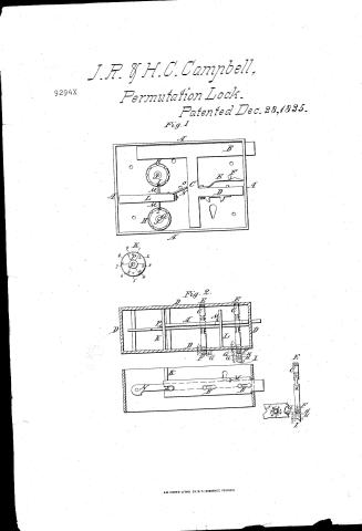
![Diagram of Permutation Lock, Fig. 1, showing components labeled A, B, C, D, E, F, H, I, K, L, M, N, P, with circular dials and mechanical parts.]
Fig. 2.
![Diagram of Permutation Lock, Fig. 2, showing cross-sections and side views of the lock mechanism with labeled parts D, E, F, K, L, M, N, P, and a key with labeled parts F, H, I, J, K, L, M, N, P, Q, R, S, T, U, V, W, X, Y, Z.]
AM. PHOTO-LITHO. CO. N.Y. (OSBORNE'S PROCESS)
Page 2.
John Read Cambell & Henry Cyrus Cambell of Charlestown, co. of Middlesex, Commonwealth of Massachusetts
Letters Patent
The Schedule referred to in these Letters Patent and making part of the same, containing a description in the words of the said John R. Cambell and Henry Cyrus Cambell themselves of their improvement in Door Locks and other fastenings.
To all to whom these Presents shall come
Be it known, that we, John Read Cambell & Henry Cyrus Cambell both of Charlestown in the county of Middlesex and Commonwealth of Massachusetts have invented a new and useful improvement on the Lock for Doors or such like fastenings, and the following is a full and exact description of the construction and operation of the said Machine as invented or improved by us.
The principle upon which we ground our improvement is, that certain points of the arrangement are to be brought to coincide before the bolt can be shot or withdrawn, which points can be so arranged that without some clue to be guided by it becomes almost hopeless to attempt their reconnection, and this clue can be given by a combination of certain figures on the outside. This known principle we improve the construction of thus, Let Fig 1. A represent the enclosing case of the Lock B the bolt or bolts. C the cross bar running across the case, and connecting the bolts. D the catch bar to contain the catches into which the key is to be applied. E the spring behind said catch bar, bearing against the point F. G the wheels which contain the numerous bolts or obstacles H. intended to perplex & also I the true points of use. J is the axis of the outside wheels fitting tightly into G. but capable of being displaced in order to move round the outside or under wheels containing the numbers.
Page 3.
when it may be desired for precaution to change the combination K, the circle of numbers on the outside case, and around the index wheels. Between the wheels G, is placed the pivot rod L, supported so as to revolve on its axle, and at one end is placed the crofs catch M, so adjusted as to pass through the open rings at the true point J by the revolution of the pivot rod L, whenever said points are brought opposite to each other.
This revolution is effected by means of the short rod N continued from the pivot rod L sufficiently far towards the crofs bar O, to touch it so that when it is applied against the side thereof, it acts as a stopper to the bolts being withdrawn when locked. It is operated on or elevated so that the crofs bar O may be shoved under it, to unlock by means of a small hook or key through the hole O and to lock it again or rather secure it after it is locked, the same hook is applied to draw it down against the side of the crofs bar. Now, by changing or turning round the index wheels on the outside so as to derange the numbers, they can scarcely be returned to their right places by any attempts, unless the proper combination of numbers is known. The index wheels O, on the outside have to each, a row of numbers around the edge and also another on the outside of the case, is adapted to them so that any two may be specified to be brought together as the clue.
We also contemplate another mode of construction which may be used separately or in conjunction with the one above described and we effect it thus. Let A, represent the in Fig. 20, having the holes B through it made by drilling two holes near to each other and cutting a communication between them, narrower than the diameter thereof. C are two or more pins extending across the case D and passing through the holes C, at which part they are flattened, leaving shoulders and thus enabled to permit the connecting slot between the holes B to slide on this flat part which can of course only be done, when
Page 4.
They are presented in that one position, two or more of these parts may be constructed on each pin and at different inclinations so as to operate as obstacles when it is desired to present them; the each one when not desired to be in use, must have a pin through it to prevent its interfering. One end of each pin is furnished with a screw C to work in the case so as to draw it further in if required in making the change; the other end is made with a pipe H, or hollow square for the reception of the key intended to turn the pipe pin, and has two or more rings G, around its circumference numbered. The key has like rings Hb and there are also to be lines I passing through these rings likewise numbered, and lastly around the case encircling the pipe pin are rings J of numbers also. K is a brace intended to keep the bolt in its place. L is a pin for the reception of the key to work in the catches M of the bolt; N is a pin for the purpose of a pivot to the flat piece O placed parallel and adjoining the bolt. O is intended to rest on the round part of the pins C when they are not in their proper position but as soon as they are, it will fall into the flat part which is made purposely longer on one side to receive it and at which time the bolt may be thrust back over a small stop P which is fixed in O to prevent it when the said pins are not rightly placed. It will be seen that by means of the numbers on the pins, the key and the case, the same changes and obstacles may be presented as in the first described mode.
What we claim as our invention and not previously known or used and for which we now ask Letters Patent is, First, the balls or obstacles on the wheels intended to perplex in attempting to find the true points. Secondly, The Index plates or wheels as applied. Thirdly, The arrangement effected by the pivot rod, with its cross catch and its short rod continued to the cross bar running across the lock after the manner already shown. These are the parts of the first mode.
We also claim in the second mode the additional flattened parts of the pins intended to present balls or difficulties as
Page 5.
provided for in the first mode, also the construction and application of the flat piece placed parallel with and adjoining the bolt as shown, and lastly the application of the rings and lines of number on the pipe and key as well as on the face of the lock as set forth.
In Testimony, that the above is a full description of the manner of constructing our improvement as invented by us, we have hereunto set our hands this eighteenth day of November in the year of our Lord One Thousand Eight Hundred and Thirty five.
Witnesses
Abt. Moore
W. A. Doak (Drawing)
J. R. Campbell
H. C. Campbell
17365 words
Published accounts: journal notice
Notice in the monthly list of patents, with remarks
Journal of the Franklin Institute, new ser., vol. 18 (1836), p. 42 · View the page
26. For a Door Lock; John R. and Henry C. Campbell, Charleston, Middlesex county, Massachusetts, December 28.
Remarks. This is a combination lock, in which certain letters, or figures, are used to regulate the parts upon which the opening of it is dependant. There is nothing new in the principle, and the arrangement is susceptible of indefinite American Patents for December, with Remarks. changes; the modes pointed out by the patentees, are the foundation of their claim to invention, and these we do not think it necessary to particularize.
About this record
- Patentee
- Jim Shaw's X-patent list
- Date
- the Name and Date index of patents, USPTO records, Jim Shaw's X-patent list
- Invention
- the Name and Date index of patents
- Listed in
- the Name and Date index of patents, USPTO records, Jim Shaw's X-patent list, the Journal of the Franklin Institute, Burke's List of Patents (1847)
- The Franklin Institute's journal spells the name differently.
- The residence comes from the Franklin Institute's journal.
- Burke's 1847 Patent Office list gives the same patent.