

Drawings and documents
National Archives restored drawings: drawing
B. Hamblet's Patent Drawing for a Brick Machine

National Archives, Restored Patent Drawings (Record Group 241) · Full-size scan at the National Archives · Catalog record
Show the text on the drawing Hide (142 words)
Words on the drawing as machine-read by the National Archives; not checked. Useful mainly for searching.
Clay & Pottery, / Brick Machines, / nes, / Portable Mold:1 In Carrier, / Scrow / Approal ohed transverse feed. / p2 / 9298-X / IB HAMBLEYT / 9298 / B rick Machine / A Frame. B. Girts. C. MortonPut D. Grinding sleaft / Patented 28th Dec 1833 / E. Fulse Moulds = Travel ways / a. Aperlurcfor the emission of the Months / H. Ctil, casting aperture / I Daslier or Follower TC. Sliar attarhento Follower closing the / aperture when Hip messing isperfarmen I. Guittle for Handley Follower / M. upper and lower I evers. N. carre ege conlaining Moulds / 0. Trough. P. Tootle d Back. / a cop where mashing intoRact.P. / R. pulley on snaftwith a Rone / another Pulley to lower Liever Towlich it-1s attached / S. stanft. / sweek / Patent offer Gr22 1808 / Mach under the direction 4th Commition / of Patents in comformity with acts. March 1537
USPTO scan
The patent as scanned by the USPTO
-
 Page 1
-
 Page 2
-
 Page 3
-
 Page 4
-
 Page 5
-
 Page 6
-
 Page 7


U.S. Patent and Trademark Office · Google Patents
Show the transcription Hide (2,342 words)
Machine transcription (LightOnOCR) of the pages as scanned by the USPTO, most of them the handwritten copies made when the records were restored after the 1836 fire. Not checked; it can misread handwriting, so compare it with the scan.
Page 1.
9298X
B. Hamblett,
Brick Machine.
Patented Dec. 28, 1835.

AM. PHOTO-LITHO. CO. N.Y. (OSBORNE'S PROCESS)
Page 2.
Dec 28 1855 9298X 287
Benjamin Hamblet Portland Maine
Letters Patent
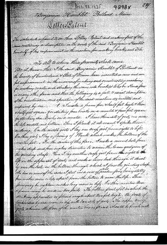
The schedule referred to in these Letters Patent and making part of the same containing a description in the words of the said Benjamin Hamblet himself of his improvement in the machine for making bricks and tile.
To all to whom these presents shall come
Be it known that I the said Benjamin Hamblet of Portland in the County of Cumberland & State of Maine have invented a new and useful improvement in the manner of making and constructing machines for making mortar and striking the same into bricks & tile by Horse power or any other power and that the following is a full & exact description of the construction and operation of the said machine as invented and improved by me
1. I make a frame five & half feet high & three & half feet square for striking four bricks in a mould & four feet square for striking six bricks in a mould. I have three sets of girts one near the top middle and bottom. Then I plank it all round & spike them strongly. On the middle girts I lay one cross girt from right to left. On these girts I lay a flooring of Plank which makes the bottom of the mortar pit. In the center of this floor I make a round hole four inches deep and four inches diameter to receive the lower guide cone of the grinding shaft. Then I lay another cross girt from right to left on the upper set of girts and make a large hole through it direct ly over the hole in the bottom through which I pass the grinding shaft. On two or more of the sides I fasten in a row of wooden pins horizontally four inches more or less apart from the bottom to near the top. These pins may be eighteen inches long more or less. On this mortar box & frame may be made in two parts. The bottom part of it in which the striking apparatus is placed may be about two feet high. The parts of timber six by six more or less with two sets of girts. The upper tier of girts above the floor of the mortar box as placed should be flush with
Page 3.
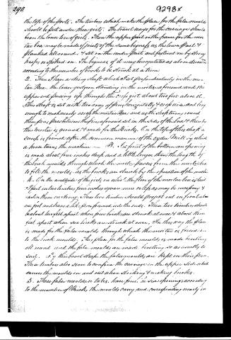
the tops of the posts. The timbers which make the place for the false moulds should be put under these girts. The travel ways for the carriage should bear the lower tier of girts. Then the upper part of the frame for the mortar box may be made of joists of the same bigness as the lower part & flanked all round. & set on the under part and fastened on by strong hasps or spiked on. The bigness of it may be regulated as above directed according to the number of bricks to be struck at a time.
2. Then I have a strong shaft which I set perpendicularly in the mortar Box. The lower gudgeon standing in the mortice aforesaid and the upper end passing up through the cross girt about two feet above it. This shaft is set with two rows of pins horizontally & one wise and long enough to reach nearly across the mortar Box and as the shaft turns round these pins pass between the pins aforesaid set in the sides of the box & then the mortar is ground & made for the Bricks. On the top of this shaft a sweep is framed after the common manner of the cyder Mill by which a horse turns the machine.
3. In front of the bottom an opening is made about four inches deep and a little longer than the length of the brick moulds through which the mortar passes from the mortar box to fill the moulds, as the bricks are struck by the operation of the machine.
4. On the underside of the girts on which the floor of the mortar box is laid I fast in two timbers four inches square more or less as may be necessary & fasten them on strong. These two timbers should project out in front about one foot and have a little piece framed into the ends. These two timbers should be about two feet apart when four bricks are struck at once & about three feet apart when six bricks are struck at once. On this way the place is made for the false moulds through which the mortar is forced on to the brick moulds. This place for the false moulds is made hexagonal all round and the false moulds are made hexagonal or as exactly to suit. By this box shape the false moulds are kept in their place. These timbers also serve to confine the carriage on the upper side which carries the moulds in and out when striking & making bricks.
5. These false moulds or tubes have four or six openings according to the number of Bricks the moulds carry and corresponding nearly in
Page 4.
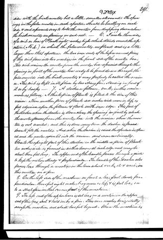
size with the brick moulds, but a little smaller all round. The openings in the false moulds in each aperture should be brelling on each side & end upwards, so as to hold the mortar from dropping down when the brick moulds are forcing in and out. — 6. I make three sides of a circle or box of plank eight inches high which stands round the aperture (No 4.) in which the false moulds are placed and is a little larger than that aperture. The two inner ends of the before named pieces of this circle pass into two mortices in the front side of the mortar box. This circle receives the mortar from the mortar box aforesaid through the opening in front of the mortar box ready to be forced down through the false moulds into the brick moulds & may properly be called this receiver. This circle is kept in its place by two strong pins standing in front of it or by hasps — 7. A dasher or follower, works in this receiver made as follows. A thick piece of plank is fitted to the size of this receiver. Then another piece of plank six inches wide more or less is put edge-wise upon the follower & flush with inner edge. This part of the dasher when the dasher is down closes the opening in front by which the mortar passes from the mortar box into the receiver when the mortar is not wanted; and this is done every time the dasher is pressed down to fill the moulds. And when the dasher is raised the aperture is opened and the mortar again let into the receiver, and so on continually. Close to the upright part of this dasher in the middle a piece of plank ten inches wide is framed in with a tenon at each edge and may be about three feet long. The upper end of this handle passes through a guide to keep the motion steady & perpendicular. The handle of this dasher also passes loose through a mortice in the lever which works it & works on this mortice on a pin. 8. On the left side of the machine in front a long post stands perpendicular, three feet eight inches long more or less & is fast loose on to a steel pin in that corner post of the machine. 9. The left end of the upper lever is set loose in a mortice in the upper end of this long post & held in by a pin. This lever reaches horizontally across the machine and about two feet beyond. When the machine is
Page 5.
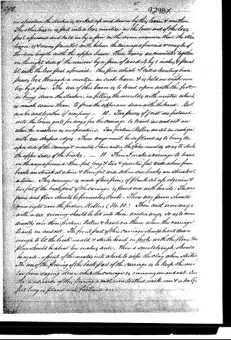
in operation the clasher is worked up and down by this lever & another. The other lever is fast into a box mortice in the lower end of the box foot aforesaid and held in by a pin in the same manner that the other lever is & runs parallel with below the carriage aforesaid & maybe of the same length with the upper lever. These levers are connected together on the right side of the receiver by a piece of wood 4 by 1 inches & parallel with the box foot aforesaid. This piece which I call a hauling brace passes loose through a mortice in each lever & is held in each mortice by a pin. The use of this lever is to tread upon with the foot in bringing down the clasher, in filling the moulds with mortar which is much easier than to press the upper one down with the hand. Both can be used together if necessary. 10. Two pieces of joist are fastened into the lower girts for ways for the carriage to travel in and out on when the machine is in operation. Two friction rollers are set in each girt with one shaped edges. These ways must be so placed as to bring the upper side of the carriage & moulds close under the false moulds so as to strike the upper sides of the bricks. — 11. Then I make a carriage to travel on the ways aforesaid three feet long & two & quarter feet wide when four bricks are struck at a time & three feet wide when six bricks are struck at a time. This carriage is made of two pieces of plank set up edgewise & two feet of the back part of the carriage is floored over with boards. The way pieces and floor should be five inches thick. These way pieces should come right over the friction rollers (No. 10.) Then cast iron ways with a row grooving should be let into these wooden ways so as to come directly over those friction rollers & travel on them when the carriage travels in and out. The front part of this carriage should be cut down enough to let the brick mould & strike board in flush with the floor. The plank should be about ten inches wide. Then a small trough should be made in front of the moulds into which to wipe the clay when striking. The use of the flooring of the back part of the carriage is to keep the mortar from caking down while the carriage is running in and out. On the underside of this flooring a cast iron toothed rack one & a half feet long is placed and fastened on.
Page 6.
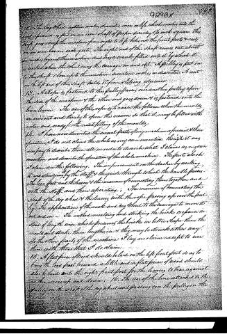
12. The cog wheel system makes a motion on a leg which makes into the end of a beam is put on an iron shaft of proper size say 1 1/2 inch square. This shaft goes across the machine from right to left behind the front posts & rests on an iron beam each gate. The right end of this shaft comes out about two inches beyond the machine and has a crank fitted into it by which it is worked when the wheel runs the carriage in and out. A pulley is put on to this shaft close up to the machine seventeen inches in diameter. A nut on the left end of this shaft holds it from slipping otherwise.
13. A Rope is fastened to this pulley passes over another pulley upon the side of the machine & the other end goes down & is fastened onto the lower lever. The use of this rope is to raise the follower when the moulds are run out and thereby to open the receiver so that it may be filled with water and ready for the next filling of the moulds.
14. I have now described the several parts of my machine as forementioned & their operation. I do not claim the whole as my own invention. Though it was necessary to describe them all in order to describe what I claim as my own invention and describe the operation of the whole machine. The parts which I claim are the following. The improvement on the dasher by working it and sliding by the staff & the guide through which the handle passes. The loss foot and the levers & the manner of connecting them together and with the staff and their operation; The manner of connecting the shaft of the cog wheel & the levers with the rope passing up over the pulley. The application of this sack and cog wheel to the carriage to move it in and out. The method moulding and striking the bricks or pieces in stead of length wise which produces the bricks in better shape than the moulds and strike them lengthwise & they may be struck either way. To the other parts of the machine I lay no claim except to use them with those that I do claim.
15. A flat piece of wood should be laid on the left front foot so as to bring the loss foot forward a little and a flat piece of wood should also be laid onto the right front foot for the levers to bear against as they move up and down.
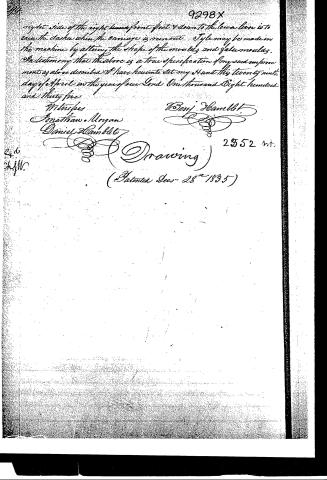
16. The use of the line attached to the pulley on the shaft of the cog wheel and passing over the pulley on the
Page 7.
right side of the right hand front foot & down to the lower line is to raise the dasher when the carriage is run out. Style may be made in this machine by altering the shape of the moulds and false moulds.
In testimony that the above is a true specification of my said improvements as above described I have hereunto set my Hand this twenty ninth day of April in the year of our Lord One thousand Eight hundred and thirty five.
Witnesses
Jonathan Morgan
Daniel Hamblet
Benj Hamblet
2352 wt.
(Drawing)
(Patented Decr 28th 1835)
Published accounts: journal notice
Notice in the monthly list of patents
Journal of the Franklin Institute, new ser., vol. 17 (1836), p. 144 · View the page
764. Brick machine. Benjamin Hamblet, Portland, Me.
Published accounts: journal notice
Notice in the monthly list of patents, with remarks
Journal of the Franklin Institute, new ser., vol. 18 (1836), p. 44 · View the page
30. For a Brick Machine; Benjamin Hamblett, Portland, Cumberland county, Maine, December 28.
Remarks. The clay is to be mixed in a box by revolving arms or knives, in the manner well known, and from the lower end of this it is to pass out through an opening to be moulded and struck. The apparatus is described at great length, and there are several distinct claims; the machine so nearly resembles some of its predecessors that any attempt at description and comparison, would demand much room, and consume more time than we have to spare. The claims alone would not furnish a correct idea of the things claimed.
About this record
- Patentee
- Jim Shaw's X-patent list
- Date
- the Name and Date index of patents, USPTO records, Jim Shaw's X-patent list
- Invention
- the Name and Date index of patents
- Listed in
- the Name and Date index of patents, USPTO records, Jim Shaw's X-patent list, the Journal of the Franklin Institute
- The Franklin Institute's journal spells the name differently.