

Drawings and documents
National Archives restored drawings: drawing
C.R. Belt's Patent Drawing for a Machine for Planting Corn

National Archives, Restored Patent Drawings (Record Group 241) · Full-size scan at the National Archives · Catalog record
Show the text on the drawing Hide (133 words)
Words on the drawing as machine-read by the National Archives; not checked. Useful mainly for searching.
Perisplanters / C.R. Belt. / :11: SEEDERS& / WIERG / Corn - -Intered- - / Patinlid 15 Janiy 1836 / 359 / [133] Walking. / ay / class / 4:3.50 / 9318.4 / DIVISION: / 93187 / managhars / Where / pointest, / H. pernoved prices. f / ach having line init which nesses over the tiolemitte / : through which the graine falls / develieving flat strins to / 71 / rank. / Houper / Herough / He'Inbert / sovered Holfier / N. plouple / 0. Encs or coulter's / Welloe to drive out the to resulate medell the of noughing / & Blnck storing on each side to keen the seencille led over the 511 cling- bars f / Re / cross. but flatstrins % with tongue J. / Patent / e connecting Rou between the / Frome a Hurron / Made under / 73 / w. cylinder,with leeth / in comformity with act / x Cord connecting of their an with connecting / Handie
USPTO scan
The patent as scanned by the USPTO
-
 Page 1
-
 Page 2
-
 Page 3
-
 Page 4
-
 Page 5


U.S. Patent and Trademark Office · Google Patents
Show the transcription Hide (1,542 words)
Machine transcription (LightOnOCR) of the pages as scanned by the USPTO, most of them the handwritten copies made when the records were restored after the 1836 fire. Not checked; it can misread handwriting, so compare it with the scan.
Page 1.
9318X
C. R. BELT.
No Printed Specification Available
Seed-Planter.
Patented Jan. 15, 1836.

AM. PHOTO-LITHO. CO. N. Y. (OSBORNE'S PROCESS)
Page 2.
Jan. 15, 1836
Charles R. Bell
Letters Patent
9318X
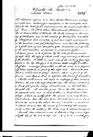
The Schedule referred to in these Letters Patent and making part of the same containing a description in the words of the said Charles R. Bell of his improvement in the machine for Planting Corn. To all to whom these presents shall come —
Be it known that I Charles R. Bell residing in the vicinity of Washington and in the district of Columbia, and state of Maryland have invented a new and useful improvement in the machine used for planting corn and that the following is a full and exact description of the construction and operation of the said machine as invented or improved by me.
A square frame is to be formed by two side pieces connected by cross bars, the size of which will vary according to the width of the bottom. A little on each side of the center of these cross bars and on the top thereof is to be placed a cross and another long bar running parallel with the sides and projecting some distance in front of the cross bars. It is intended that a wheel should play between them in front of the frame, and beyond that is applied the point of wrought.
Bells will secure the cross on springs of these pieces by between the side and the long parallel bar, the space is closed by a broad flat groove resting at each end on the cross bar beneath it. A similar groove lies on the other space on the opposite side and in each of them a long sliding bar plays, which very easily fits the groove and may be somewhat shorter than the side bars, but will project on both towards the inside of the wheel having a wheel on each end to which it is united by means of connecting bars and pivots joints so that the motion of the sliding may be always horizontal beneath. These slides and grooves are placed on long narrow hogshead legs for the seed to drop into. If by turns across the frame.
Page 3.
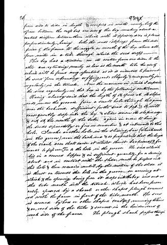
from side to side in length & occupies in width nearly half the space between the rows has one side of the box making about a central division between them which with its opposite side is placed perpendicularly having both the rows sloping from the side faces of the frame to the nozzle or mouth of the box where all four unite in a tube through which the seed drops.
This box has a division in its center from one side to the other and extending nearly as low as the mouth tube the use of which will be found very essential as it is intended to prevent the seed from rebounding or flying out obliquely & consequently irregularly in the trough. Now the manner in which I deposit the seed regularly in this box is by the following contrivance.
Having already said that the length of its opens at its sloping ends near the ground, form a small hole through this groove near the back end sufficient for the seed to pass & it will consequently drop into the box & slides down its slope edge & out at the mouth of the tube again in order to bring the seeds separately or free in number & at intervals to the hole. I make another hole in the sliding bar (which works in this groove) near the back end & so proportion it that the length of the crank arm shall cause it whilst thrust backwards & forward to proportion to the hole in the groove. The seed which lies in a conical hopper & in sufficient quantity for a serving about one in contact with the slide, must be pushed into this hole & then remains until by the motion of the slide it is thrust on towards the hole in the groove, an opening at which & the opening being free it drops into the box and out at the tube mouth into the trough which has been previously opened by a shovel or other shaped plough connected with the frame in front of the tube mouth. The seed is covered by two or other shaped covers remaining behind & on each side of the tube & remains in the hinder end of each side of the frame. The plough shank passes through
Page 4.
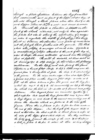
through a plate fastened between the long parallel bars underneath and in front of the hopper shaped box, it also rises through a block placed above these bars in the rear hopper where at its end is a nut and screw to receive it. Beneath the plate a shoulder is placed on the back of the shank intended not only to bear against the plate but also to allow of the application of a wedge in order to regulate the depth of ploughing this being thrust in between the shoulder and plate of course drives out the plough blade further into the ground. The block above also slopes to an edge at each side, opposite to a corresponding slope attached to the end of the box in order to keep the seed collected as much over the sliding bars as possible. It will be desirable at times such as at sowing etc to stop sowing for this I have the following contrivance. On the top of each side piece of the frame is fastened a broad flat strip to lap a little way over the ground piece & thereby hold it fast. The strip to be about as long as the groove. On the inner inner edge where it so laps I form a groove and place another tongue flat strip so wide as to fill up the space between or from this groove and the long parallel bar next to it & to lie immediately on top of the sliding bar which has the hole in it so close as to prevent seed getting between. These tongue pieces are connected together by a short strip bar laid across the long parallel ones & from this a long tongue or rod leads to the various connecting rods between the handles which are fastened to the sides of the frame. There then is placed a pin to fit the holes made in the end of this tongue. Now the length of the tongue strips is such as that when the short strip bar is thrust forward as far as the side of the hopper of seed which stops it, then they will cover the holes next forward the escape of the seed. & at this point a hole is filled to the pin to retain it there as long as desired.
Page 5.
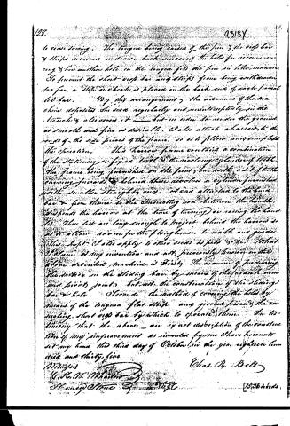
to cease sawing. The tongue being raised by the pin & the edge bar & strips removed or drawn back uncovers the hole for recommencing & has another hole in the tongue fits the pin in like manner. To prevent the short edge bar and strips from being withdrawn too far, a stop or cheek is placed on the back end of each parallel slot bar. By this arrangement the advance of the machine deposits the slots regularly and uninterruptedly in the teeth & also covers it— but in order to render the ground as smooth and fine as desirable, I also attach a harrow to the ends of the side pieces of the frame, so as to follow and complete the operation. This harrow frame contains a combination of the stationary or fixed teeth & the revolving cylinder of teeth. The frame being furnished on the front bar with a set of teeth turning forwards & behind there revolves a cylinder furnished with smaller straight ones. A cord attached to the hand bar & from thence to the connecting rod between the handles, suspends the harrow at the time of turning or raising the handles. These bars are long enough to project behind the harrow so as to allow room for the ploughman to walk and guide the shaft. I also apply to other uses as just &c. &c. What I claim as my invention and not previously known in the above described machine is Firstly The manner of producing the motion in the sliding bar by means of the screw and pivot joints but not the construction of the sliding bar & hole. Secondly The method of covering the holes by means of the tongue flat strips and groove pieces & the revolving short edge bar by which to operate them. In testimony that the above are exact description of the construction of my improvement as invented by me I have hereunto set my hand this third day of October in the year eighteen hundred and thirty five.
Witnesses
G. H. M. Maitland
Henry Stone
Chas. R. Bell
25th October
Published accounts: journal notice
Notice in the monthly list of patents, with remarks
Journal of the Franklin Institute, new ser., vol. 18 (1836), p. 115 · View the page
14. For a Machine for Planting Corn; Charles R. Belt, Washington county, District of Columbia, January 15.
Remarks. There are many patented machines for planting corn, cotton, and other seeds, so nearly resembling each other, as to constitute different modifications only of the same machine, and such is the character of the one before The claims made are confined to two particular points in which the patentee considers his machine as excelling its predecessors, but its superiority not being apparent to us, we shall pass on to other matters. us.
About this record
- Patentee
- DATAMP
- Date
- the Name and Date index of patents, DATAMP, USPTO records
- Invention
- DATAMP
- Listed in
- the Name and Date index of patents, DATAMP, USPTO records, Jim Shaw's X-patent list, the Journal of the Franklin Institute, Burke's List of Patents (1847)
- Burke's 1847 Patent Office list gives the same patent.