

Drawings and documents
USPTO scan
The patent as scanned by the USPTO
-
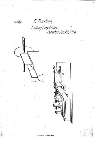 Page 1
-
 Page 2
-
 Page 3
-
 Page 4


U.S. Patent and Trademark Office · Google Patents
Show the transcription Hide (773 words)
Machine transcription (LightOnOCR) of the pages as scanned by the USPTO, most of them the handwritten copies made when the records were restored after the 1836 fire. Not checked; it can misread handwriting, so compare it with the scan.
Page 1.
9330½x
C. Buckland,
Cutting Corset Rings,
Patented Jan. 20, 1836.
AM. PHOTO-LITH. CO. N.Y. (GIBBONS PROCESS)
Page 2.
Jan. 20 1836
Charles Buckland
Letters Patent 9330½X
No 25.
The Schedule referred to in these Letters Patent and making part of the same containing a description of in the words of the said Charles Buckland himself of his improvement in the machinery for cutting Grooves in Corset-rings and other articles
To all to whom this present shall come.
Be it known that I, Charles Buckland of Middletown in the county of Middlesex and State of Connecticut have invented a new and useful improvement in Machinery for cutting grooves in Corset-rings of bone ivory or other substance and grooves in rings, wheels and round blocks of any other material in description and that the following is a full and exact description of the construction and operation of the said Machine as invented or improved by me.
A frame of cast iron called the bed (Marked A in the annexed drawing) twelve inches long and eight and a half inches wide is fastened to a bench with screws.
Inside of this frame, one on its rails is fitted another frame of cast iron (Marked B) seven and a half inches long and five and a half inches wide and so adjusted as to slide on the rails at pleasure.
This inner frame is confined down to the rails by means of two iron plates (Marked C,C) with screws called the slide-rest. On the side of the slide-rest opposite to the front part of the frame are fitted two small rods of iron and on these rods two spiral springs so that as the operator pushes the slide out from him these springs by their equal construction enable him to move the slide not slowly up to the same as cutting.
Rm.
Page 3.
12.
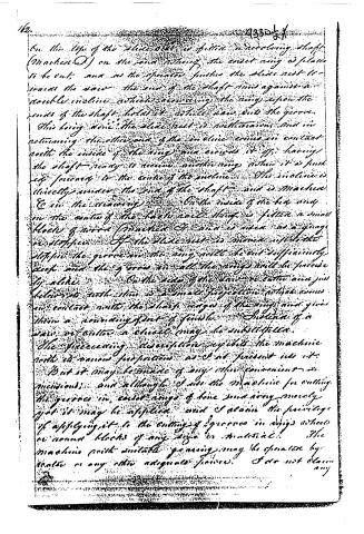
On the top of the slide block is fitted a revolving shaft (Marked O) on the end, whereby the end of any is placed to be cut; and as the operator pushes the slide nest to-wards the saw, the end of the shaft runs against a double incline which conveying the ring upon the ends of the shaft, holds it while saw cuts the groove.
This being done, the slide nest is withdrawn, and in returning, the other end of the incline comes in contact with the inside of the ring, and crowds it off, leaving the shaft ready to receive another ring when it is pushed forward to the centre of the incline. The incline is directly under the end of the shaft, and is Marked E in the drawing.
On the inside of the box, and on the centre of the back rail, there is fitted a small block of iron (Marked G) and is used as a gauge or stopper. If the slide nest is moved up to the stopper, the groove in the ring will be cut sufficiently deep, and the groove in all the rings will be precise by alike.
On the side of the saw, to cutter and just below its teeth, there is a small projection which comes in contact with the sharp edges of the ring, and gives them a revolving sort of finish. Instead of a saw, or cutter, a chisel may be substituted.
The foregoing description exhibits the machine with its various proportions, as it at present is.
But it may be made of any other convenient dimensions; and although I use the machine for cutting the grooves in cast rings of bone and ivory merely, yet it may be applied, and I claim the privilege of applying it to the cutting of grooves in ships wheels or round blocks of any size or material. The machine with suitable gearing, may be operated by water or any other adequate power. I do not claim any
Page 4.
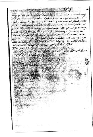
any of the parts of the said Machine taken separately, as my invention, but I do claim as my invention and improvement the combination of the several parts of the said Machine in the manner above specified, to produce said thereby furnishing the effect of cutting with rapidity, neatness and uniformity, grooves in Coiled rings of bone, ivory or other substance, and grooves in rings, wheels and round blocks of any other material or composition. Dated at Middleton the tenth day of August A.D. 1835.
Witnesses:
Horace Clark
John Davis
Charles Buckland
Dr.
76000
167
453057
(44)
1141
Published accounts: journal notice
Notice in the monthly list of patents, with remarks
Journal of the Franklin Institute, new ser., vol. 18 (1836), p. 118 · View the page
25. For Cutting grooves in Corset rings of Bone, Ivory, &c., and also in other articles; Charles Buckland, Middletown, Middlesex county, Connecticut, January 20.
Remarks. The ring to be cut is placed upon the projecting end of a revolving mandrel, the frame of which is made to slide so that the ring may be brought up against a revolving saw, or cutter, which cuts the groove. The appendages for adapting it to the purpose to which it is applied, are represented and described, and the combination of the several parts constitutes the claim.
About this record
- Patentee
- the Journal of the Franklin Institute, Journal
- Date
- the Name and Date index of patents, USPTO records
- Invention
- the Name and Date index of patents
- Listed in
- the Name and Date index of patents, USPTO records, the Journal of the Franklin Institute
- The Name and Date index has a note on this number.
- The patentee's full name comes from the Franklin Institute's journal.
- The residence comes from the Franklin Institute's journal.