

Drawings and documents
USPTO scan
The patent as scanned by the USPTO
-
 Page 1
-
 Page 2
-
 Page 3
-
 Page 4
-
 Page 5
-
 Page 6


U.S. Patent and Trademark Office · Google Patents
Show the transcription Hide (1,805 words)
Machine transcription (LightOnOCR) of the pages as scanned by the USPTO, most of them the handwritten copies made when the records were restored after the 1836 fire. Not checked; it can misread handwriting, so compare it with the scan.
Page 2.
United States Patent
Patent No.: X9348
Isaac & Hedges, Clinico. N. York.
Letting Patent
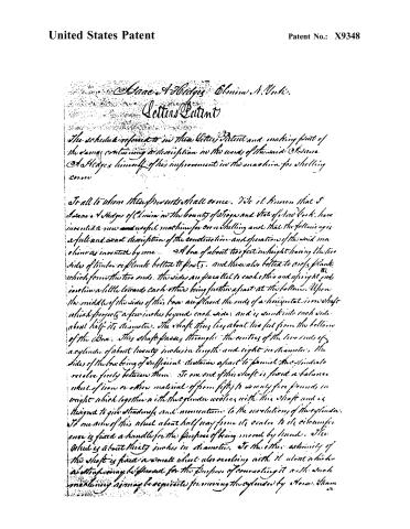
The schedule referred to in this Letter Patent and making part of the same, containing a description in the words of the said Isaac & Hedges himself of his improvement in the machine for shelling corn.
To all to whom these presents shall come. We it known that I Isaac & Hedges of Clinico in the county of St. John and State of New York, have invented a new and useful machine for corn shelling and that the following is a full and exact description of the construction and operation of the said machine as invented by me.
A box of about two feet in height having the two sides of timber or plank bolted to posts, and there also bolted to cross planks which form the two ends, the sides are parallel to each other and upright and incline a little towards each other being further apart at the bottom. Upon the middle of the sides of this box are placed the ends of a horizontal iron shaft which projects a few inches beyond each side, and is sunk into each side about half its diameter. The shaft thus lies about two feet from the bottom of the box. This shaft passes through the centres of the two ends of a cylinder of about twenty inches in length and eight in diameter, the sides of the box being of sufficient distance apart to permit the cylinder to revolve freely between them. To one end of this shaft is fixed a balance wheel of iron or other material of from fifty to seventy-five pounds in weight which together with the two planks revolves with this shaft and is designed to give steadiness and momentum to the revolution of the cylinder. To one side of this wheel about half way from its center to its circumference is fixed a handle for the purpose of being moved by hand. The wheel is about thirty inches in diameter. To the other extremity of the shaft is fixed a small wheel also revolving with it about which a strap may be placed for the purpose of connecting it with such machinery as may be requisite for moving the cylinder by horse, steam or
Page 3.
United States Patent
Patent No.: X9348
waterproof. When these, staves or antiprises is used the balance which may, if judged necessary be hinged from the shaft. The cylinder is formed of cast iron staves. Upon its concave surface are small protuberances of about one fourth of an inch in height arranged at moderate intervals in parallel rows at short distances from each other, now or existing, of two lines as nearly straight as may be inclining towards the direction in which the cylinder revolves meeting midway between the two ends of the cylinder and forming there an angle of about one hundred and fifty degrees with each other. The iron staves which form the surface of the cylinder are secured by wrought iron bands passing round the ends of the cylinder. A concave iron sheeting cylindrical surface lying horizontally and having its upper edges in the same horizontal plane. This surface is of sufficient extent to cover nearly the whole of the lower half of the cylinder and when in its natural position the space between the cylinder and that edge of this surface at which the case of cover resting in order to close between them the cylinder is about one and one fourth inches, gradually diminishing till at the opposite edge when the cover leaves the cylinder this space is about five eighths of an inch. These spaces mentioned are scattered from the general surface of the cylinder to the summit of the ridge to be avoided in the concave surface, and these spaces may be increased or diminished in proportion to the size of room in different countries. This concave surface consists of two or more rectangular plates each running the whole length of the cylinder and ending a semicircular line of motion made on a cast iron plate which is attached by bolts to the inside of the box on each side. These two plates also assist in forming a support to the shafts of the cylinder. About one inch of moving of each stave is turned upwards to pass behind the cast plate just mentioned thus preventing the bottoms of cases from interfering with the springs attached to the backs of the staves. These springs may be of wood or of steel and are about three fourths of an inch broad. If of wood one spring is attached to the back of each stave by screws and extends both ways leaving a little from the shaft
Page 4.
United States Patent
Patent No.: X9348
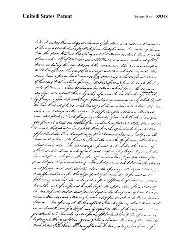
It is to enter the mortises at the end of the slats and rest on the sides of the mortises which is farthest from the cylinder. In entering the mortise the space between the spring and the slats is about three-fourths of an inch. If of these two are attached, one more, each end of the slats entering the mortises in like manner. The concave surface will thus press the way of corn against the cylinder and at the same time spring back more or less according to the different sides of the corn & at no time pressing with sufficient force to break the fine nuts of corn. These rectangular slats which form the concave surface are about three-eighths of an inch in thickness & are strengthened by flanges affixed to each edge of the slats and running its whole length within the end plates, meet the edges of the mortises into which the slats enter and confines the slats to its proper place between the end and side plates. Each flange is about 1/4 of an inch thick, one flange projects about one eighth of an inch below that end of the slats which is next the cylinder and about three-fourths of an inch beyond the opposite side. Thus strengthening the slats and forming ridges in the concave surface. The breadth of each slat with the flanges attached is about two inches. The slats are perforated with holes, the number of which are about one inch apart and sufficiently large to permit the kernels of corn to pass through. Space is also left for the same purpose between the mortises. The holes are made between the spring and flange and not directly above the spring, & second too, a hopper and cover for the upper part of the cylinder is formed in the following manner. The rectangular pieces of plank of about one foot in breadth and of sufficient length to join the upper edges of the sides of the box, be fastened and joined together by two pieces of board so as to form a trough, each other side from a hopper in which to throw the corn. The opening at the lower part of this hopper is about three inches in breadth and of a length nearly equal to that of the cylinder. A rim is attached to the rectangular pieces of plank to limit the opening as to prevent the corn from falling between the ends of the cylinder and sides of the box. Having placed the two rectangular pieces of
Page 5.
United States Patent
Patent No.: X9348
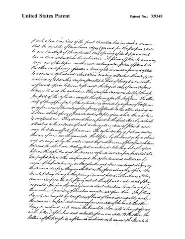
Plants upon two sides of the first described box in such a manner that the middle of their lower edges (grooved for the purpose) will be over the shaft of the cylinder. This opening of the hopper about two or three inches above the cylinder. A piece of plank running from one of the boxes mentioned, rectangular pieces of plank to the other and firmly fixed — having its inner surface adapted to a concave cylindrical shaft. One coating attached. This is so inclined as to have this surface parallel to that of the cylinder with sufficient space between to permit the largest calyx of corn to pass between it and the cylinder. This surface covers one half of the shaft part of the cylinder except the opening for the hopper. The other half of the shaft part of the cylinder is covered by a piece of board running from one of the rectangular pieces of plank to the other serving as a door which opens upward and is kept open while the machine is in operation. This second box is fixed to the first box by a bolt attached to the outside of each rectangular piece of plank and may be taken off at pleasure. The cylinder being put in motion the ears of corn are thrown into the hopper by the hand or by a chain and are carried by the motion and the rotation of the cylinder between the two described non-coating just mentioned like they slide in the space between the cylinder and the concave cylindrical surface just described. Compressed between this surface and the cylinder and rolled over by means of the protruberances in the cylinder and above mentioned ridges on this concave surface. They are shelled as they pass along this space. The kernels falling through the opening inward between the slats of this concave surface. The only flying out into the opposite side and of them as would otherwise fly out in a vertical direction being turned from the machine by means of the above mentioned open door. The falling kernels are caught by two pieces of board placed immediately under the concave surface and running from one side of the box to the other being so inclined as to cause the kernels to slide into a trough placed on the bottom of the box and extending from one side to the other. The bottom of this trough is a plane so inclined as to cause the kernels to
Page 6.
United States Patent
Patent No.: X9348
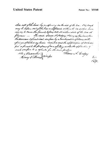
slide out of the box by an opening in the side of the box. This trough may be taken out of the box and placed within it in such a manner as to cause the items to pass out at either side of the box at pleasure. — The said Isaac A. Hedges claims as his invention the concave cylindrical surface by a combination of slugs with springs attached as herein described and the application of such surface as found to the functions of a snelling as also the application of such surface to a cylinder for the same purpose.
Isaac A. Hedges
Henry W. Bree, Witness.
E. i
Chf. Sr.
Published accounts: journal notice
Notice in the monthly list of patents, with remarks
Journal of the Franklin Institute, new ser., vol. 18 (1836), p. 183 · View the page
6. For a Machine for Shelling Corn; Isaac A. Hedges, Elmira, Tioga county, New York, February 3.
Remarks. This machine, in its general principles, resembles the first shelling machine which was patented. It has a revolving cylinder and a concave, between which the ears of corn are to be shelled. The cylinder is to be formed of cast-iron staves, having teeth upon it, and the concave is also of cast-iron staves, with spaces between them for the escape of the grains of corn; the concave is borne up by springs. The ears are to be put into a hopper above the cylinder, and to be conducted through a proper aperture to the shelling part. The claim is to "the concave cylindrical surface by a combination of staves, with springs attached as herein described; and the application of such surface so formed to the purposes of corn shelling; as also the application of such surface to a cylinder for the same purpose."
About this record
- Patentee
- DATAMP
- Date
- the Name and Date index of patents, DATAMP, USPTO records
- Invention
- DATAMP
- Listed in
- the Name and Date index of patents, DATAMP, USPTO records, Jim Shaw's X-patent list, the Journal of the Franklin Institute, Burke's List of Patents (1847)
- Burke's 1847 Patent Office list gives the same patent.