

Drawings and documents
National Archives restored drawings: drawing
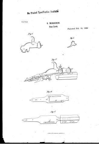
Samuel Morrison's Patent Drawing for a Gun Lock

National Archives, Restored Patent Drawings (Record Group 241) · Full-size scan at the National Archives · Catalog record
Show the text on the drawing Hide (43 words)
Words on the drawing as machine-read by the National Archives; not checked. Useful mainly for searching.
42. FIRE-ARMS / you / [66] Locks. / CLASSITICATION / SAMUEI / 9378-X / DIVISION. / G UN LOCKS. / th / Patented 10 / Feb / 1836 / z. / Fig 2. / B. / Fig.3. / OH / IT / Fig. 4. / Fig.5. / OA / B.O / C. / D. / bB
USPTO scan
The patent as scanned by the USPTO
-
 Page 1
-
 Page 2
-
 Page 3
-
 Page 4
-
 Page 5


U.S. Patent and Trademark Office · Google Patents
Show the transcription Hide (1,365 words)
Machine transcription (LightOnOCR) of the pages as scanned by the USPTO, most of them the handwritten copies made when the records were restored after the 1836 fire. Not checked; it can misread handwriting, so compare it with the scan.
Page 1.
No Printed Specification Available
9378X
S. MORRISON.
Gun Lock.
Patented Feb. 10, 1836
Fig 1
Fig 2
Fig 3
Fig 4
Fig 5
Page 2.
Feb. 10, 1836 9378X.24
Samuel Morrison, Northumberland, Pa.
Letters Patent.
The schedule referred to in these Letters Patent and making machine part of the same containing a description in the words of the said Samuel Morrison himself of his improvement in the Gunlock, for discharging one or two loads from one barrel.
To all to whom these presents shall come: Be it known that I, Samuel Morrison, of Milton in the County of Northumberland and State of Pennsylvania have invented a new and useful improvement in Gun Locks, and in the mode of applying them so as to discharge either one or two loads from a single barrel at one and the same time, and that the following is a full and exact description of the construction and operation of said machine as invented or improved by me. The invention or improvement consists of a lengthened British pin (A, B, Figures 1 & 2), a Lever (Fig. 2), a dog (Fig. 3 & 4), a main spring (A & B, Fig. 5 & 2), a set screw (D, Fig. 3 & 4), and a trigger (C, Fig. 2) for the purpose of regulating the force of the main spring and in connecting these in such manner with the British pin and with each other, that when the trigger is pulled one or two loads may be discharged from a single barrel at one time without the necessity of their being either two locks or two locks. — The British pin (A & B, Fig. 3 & 2) is made about the width of the barrel, and for a common size a gun enters about five inches along the British of the gun. Near the right side of the British pin a hole (E, Fig. 3 & 4) is made for the admission of the lever which is secured therein by and revolves upon a pivot (F, Fig. 3 & 4) so that when the Lever is raised or cocked the nose of the dog (2) is pressed into the notch (3) of the lever by the action of the main spring, and thus secures the Lever until by pulling the trigger the nose of the dog is dislodged, and allows the lever to be thrown by the force of the main
Page 3.
218.
9376X
Main-spring (t.B) upon the percussion grain powder caps and thus causes the explosion or discharge. The main spring is fastened by a screw (c fig 4) upon the underside of the britch-pin, and in such a manner as to press sufficiently hard upon the dog (d fig 3) to throw it nose into the notch (S) of the lever when the latter is raised or racked. The dog works upon the underside of the britch-pin upon a pivot P. The set screw (Q) is for the purpose of regulating the rising of the dog, and thus enables the gunner to shoot with a light or strong finger as occasion may require. The main spring is also secured by a pivot (R) in the underside of the britch-pin, and by turning the gauge screw G which presses upon it at (W) its force or strength is increased or diminished at the pleasure of the gunner.
The Britch-pin is let into the butt of the gun and secured by two screws (S & T fig 6) passing through the same into the end of the britch so that when a gun is finished and ready for use the main spring, dog and main spring are enclosed within the britch, and of course nothing belonging to the lock itself is visible but the upper surface of the britch-pin, the head of the set and gauge screws and the lever. Upon the upper side of the lever there is a projection (t fig 1) forming part of the same, and designed as a means of raising or cocking it a little in advance or at the fore part (O) the lever is made in the shape of an inverted bowl, which falls upon the cap, and at the time of its explosion prevents the fragments from injuring the gunner. The tube in which the cap is placed is secured into a shoulder (O or fig 6) formed upon the right hand side of the barrel so that it can be removed at pleasure for the admission of another tube calculated for firing the percussion grain powder. Through the bowl of the lever there is also a hole made for the insertion of either a screw with a point for the explosion of percussion grain powder or one for the explosion of caps, so that either can be used at the will of the gunner. The invention or improvement further consists in constructing the lever and a second tube.
Page 4.
And in placing them in such a manner as to shoot off either one or two loads from a single barrel at one time, a barrel calculated for these purposes has the diameter of the bore for the first charge, made smaller than the diameter for the second and the rest of the above. The length of the bore for the first charge must be of a size proportionate to that of the gun, and near the shoulder and the tube I fig 37 in which the explosive powder is placed for igniting the second charge is placed sufficiently in advance of the shoulder and tube H to have its touch hole opening upon the second charge, a little more than the diameter of the larger bore, from the shoulder which the smaller one enters at its place of connection with the larger bore.
The two bores as also the place for a bullet belonging to the first charge is represented by the dotted lines on the base of fig 37. The load for a gun calculated for shooting two loads has two bowls (A & B fig 38), the one sufficiently in advance of the other to suit the relative situation of the tubes. And in order at any time to shoot off either one or both loads at a time, one of the bowls is made with a revolving block (A) connecting through the top of the bowls with a thumb piece (B) so that when placed as represented in the figure both loads can be discharged at once, but when the block is turned half round by the thumb piece so that the part A takes the place now occupied by the part B and does not touch the tube, the forward load only is discharged because when the block is in this last mentioned situation the forward bowl is not prevented by the block from being full upon the forward tube. The revolving block may be put into either the forward or hindmost bowl of the bore, and the latter may be made without the movable piece through the bowls, if only one kind of priming is to be used. What I claim as my own invention and not previously known or used in the above described Machine are first extending the bullet pin more
Page 5.
220.
9378X
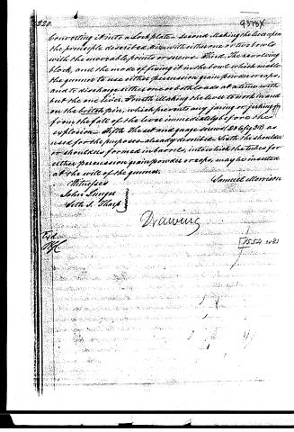
Converting it into a lock plate—Second, making the lever upon the principle described, with either one or two bowls with the movable points or screws—Third, the revolving block, and the mode of fixing it in the bowl which enables the gunner to use either percussion grain powder or caps, and to discharge either one or both loads at a time with but the one lever. Fourth, making the lever to work in and on the britch piece, which prevents any jarring or jerking from the fall of the lever immediately before the explosion—Fifth, the set and gauge screws (206 fig 21) as used for the purposes already described. Sixth, the shoulder or shoulders formed in barrels, into which the tubes for either percussion grain powder or caps, may be inserted at the will of the gunner.
Witnesses
John Langer
Wm. S. Sharp
Samuel Morrison
Drawing
Tid.
MC
1554 1085
Published accounts: journal notice
Notice in the monthly list of patents, with remarks
Journal of the Franklin Institute, new ser., vol. 18 (1836), p. 188 · View the page
30. For an improvement in Gun Locks; Samuel Morrison, Milton, Northumberland county, Pennsylvania, February 10.
Remarks. One object in this lock is to enable the gunner to fire off either one or two loads at the same time, or at separate times, from a single barrel. The first load is received in a chamber somewhat smaller than the general bore of the gun, and the charge is covered by its ball, after which the second load is rammed down; there must be two cups for percussion powder, or nipples for two caps, with a contrivance to prevent the discharge of the first charge, when one only is to be fired off. There are six separate claims to distinct parts of the lock and its appendages, which we do not think it necessary to give. It has been repeatedly proposed to place several charges in a single barrel, to be fired in succession, and the mode of effecting it has been described, but there, we believe, the matter has ended, and is likely again to end.
About this record
- Patentee
- DATAMP
- Date
- the Name and Date index of patents, DATAMP, USPTO records
- Invention
- DATAMP
- Listed in
- the Name and Date index of patents, DATAMP, USPTO records, Jim Shaw's X-patent list, the Journal of the Franklin Institute, Burke's List of Patents (1847)
- Burke's 1847 Patent Office list gives the same patent.