

Drawings and documents
National Archives restored drawings: drawing
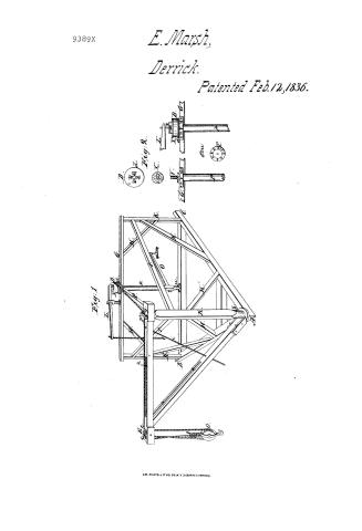
E. Marsh's Patent Drawing for an Improvement in the Crane

National Archives, Restored Patent Drawings (Record Group 241) · Full-size scan at the National Archives · Catalog record
Show the text on the drawing Hide (51 words)
Words on the drawing as machine-read by the National Archives; not checked. Useful mainly for searching.
Education any ECO Traws FLD 1 erricks S / MARSH / 57. & DERRICKS, / RLS., / Support, / 'ing, / Improvement in the Crane. / Patented Tieb.12th 1836. / CLASSIFICATION / 9389x / DIVISION / 9389 X / Fig: get / Is / The / L. / 30 / Ht / Scale 4efeet to one Inch
USPTO scan
The patent as scanned by the USPTO
-
 Page 1
-
 Page 2
-
 Page 3
-
 Page 4
-
 Page 5


U.S. Patent and Trademark Office · Google Patents
Show the transcription Hide (1,194 words)
Machine transcription (LightOnOCR) of the pages as scanned by the USPTO, most of them the handwritten copies made when the records were restored after the 1836 fire. Not checked; it can misread handwriting, so compare it with the scan.
Page 1.
9389X
E. Marsh,
Derrick.
Patented Feb. 12, 1836.

AM. PHOTO-LITHO. CO. N. Y. (OSBORNE'S PROCESS)
Page 2.
Feb. 12, 1836 9389X
Elias Marsh, Oswego New York.
Letters Patent.
The schedule referred to in these Letters Patent, and making part of the same, containing a description in the words of the said Elias Marsh, himself of his improvement in the crane for elevating and removing heavy bodies.
To all to whom these presents shall come; Be it known that I, Elias Marsh of the town of Oswego in the county of Oswego and state of New York, have invented a new and useful improvement in the crane for removing & elevating heavy bodies, and for other purposes, and that the following is a full and exact description of the construction and operation of the said crane as invented or improved by me. The principal parts of the Machine are the frame, the Boom and arm, the drum, the shaft and the loose. First the frame (see fig 1 a perspective drawing of the machine) is constructed of three substantial till pieces, tinned together in form of a triangle A.B.C. which I prefer making rectangular at its the angle at which the arm is to be placed, from each angle rises a strong upright timber K, tinned into the till pieces and receiving at their upper ends the side rails S.S. and cap pieces C. Braces B.B. are also added for the purpose of stiffening the frame, and a strong brace or cross piece P extends from the top of the upright at the right angle C (which for distinction I shall call the king post) to the middle of the cap pieces C-2 na-
The arm and Boom the first S.S. is made of a square piece of timber, of dimensions proportioned to the work for which the crane is to be employed, with one or more pulleys &c. at the lower extremity &c. to receive the hoisting rope which passes to the block O and a double leading pulley S at the inner extremity
39
Page 3.
114.
9389X
D by which the hoisting rope (r) from the drum is always kept on the arm and the force thus made to act in the direction of its length and of the brace P. A hole is also bored on the underside of the end D which receives a strong iron guigeon made fast in the top of the king post upon which the arm traverses as a centre of motion; the Boom B. descends obliquely to the foot of the king post against which it bears, being kept in place simply by a semicircular notch either cut out of the solid or formed by wooden lams bolted on the sides of the Boom; the foot of the post being also rounded so as to allow the boom to traverse freely and without much friction also for the same purpose a projecting collar of iron or hard wood is placed at the foot of the post which receives the downward bearing of the boom. For strengthening the boom as well as for convenience in handling the crane when unshipped it is connected near the middle down with the inner end of the arm by a strong bar t, of iron or wood 3rd. The Drum D is made of a solid cylinder of hard wood of suitable dimensions, it is pierced through the centre its whole length to receive the iron guigeon o of the shaft P, on the lower end is bolted a disk of iron indented as hereinafter mentioned (d. see fig 3) having a hole h for the passage of the guigeon, at, also projects a short distance beyond the cylinder forming a flange to keep up the rope. The top is covered with a circular iron plate X, having at the centre a staple Y, and a wrist pin which latter is fastened to a small lever L, secured to the top of the frame above the drum by which the latter can be raised or lowered and the coupling with the shaft be thrown out, or into gear at pleasure. From the shaft P is of wood having a strong iron guigeon o in the upper end, which wrist passes into the drum the whole length of the latter and forms a shaft.
Page 4.
or spindle upon which the drum turns loosely, upon the top of the shaft is secured a disk or coupling, where the teeth or knobs of which 411, match the cinks 3.2.3 of the disk on the drum, the upper end of the shaft is confined against the cap piece & by a suitable box and screw bolts & and the lower end has a short guage which is stepped into the centre of a solid horizontal ratch wheel T secured to the middle of that side under the cap piece & a pale U, is attached to the foot of the shaft which takes in the ratch T and prevents the shaft from running back. A strong lever Q is mortised into the shaft to which the moving power is applied. The machine being placed in a suitable position the body to be raised is attached to the hook of the block O, and the shaft p, put in revolution either by horse, hand or other power when the weight is raised to the desired height. The arm is turned to the required position and the drum being raised by the lever L, the body is securely deposited without the delay & trouble of re-engaging the shaft and moreover during the whole operation the force being made by the peculiar construction of the machine, to act very nearly in the direction of the length of the arm and of the brace P. it will operate equally well in any position of the arm. When the machine is to be used in lifting up old canal locks or similar work, the arm and boom are each to have a groove for the passage of the rope, and a pulley or pulleys moveable along the top of the arm are to be used in lieu of the fixed pulleys &c.-
Now what I claim as new and as my invention is the coupling of the drum and the peculiar arrangement by which the arm is left free to move whilst the force is operating, or by which the force applied is made to act & react in the direction of the arm and connecting brace P, in any position of the arm, without the inclusion of that rope, wire classes &c. attached to the
Page 5.
216.
From as in ordinary use. In testimony that the foregoing is a true specification of my said improvement, I have hereunto set my hand this 3rd day of January 1836.
Witnesses
Clement J. Boste
George J. Boste
Elias March
Drawing
F389X
[200 108]
Published accounts: journal notice
Notice in the monthly list of patents, with remarks
Journal of the Franklin Institute, new ser., vol. 18 (1836), p. 191 · View the page
42. For a Crane for moving heavy bodies; Elias Marsh, Oswego, Oswego county, New York, February 10.
Remarks. In this crane the power is applied to a horizontal lever attached to a vertical shaft, in the manner of the common horse mill. At the upper end of this shaft there is a drum, round which the hoisting rope is to coil. The other end of the rope extends to the outer extremity of the arm of a common crane, and leads over pulleys in the ordinary way, to a block. Over the shaft of the crane there are two guide pulleys for the hoisting rope, keeping it in its place as the crane is turned in any direction. The drum at the upper end of the first named shaft, turns upon an iron gudgeon, and rests upon a coupling box, so that when the load has been raised, and the crane is turned to the point where it is to be dumped, by pulling on a lever the drum is disengaged from the coupling box, and the load descends. The claims are to "the arrangement by which the arm is left free to traverse whilst the force is operating, or by which the force applied is made to act and react in the direction of the arm, without the intervention of check ropes, windlasses, &c., attached to the boom, as in ordinary use." So far as this applies to the allowing the crane to turn freely whilst the hoisting rope is kept in its place by the guide pulleys, there is no novelty in the thing, and it seems to us as though this was mainly alluded to.
About this record
- Patentee
- DATAMP
- Date
- the Name and Date index of patents, DATAMP, USPTO records
- Invention
- DATAMP
- Listed in
- the Name and Date index of patents, DATAMP, USPTO records, Jim Shaw's X-patent list, the Journal of the Franklin Institute, Burke's List of Patents (1847)
- The Franklin Institute's journal gives a different date.
- Burke's 1847 Patent Office list gives the same patent.