

Drawings and documents
National Archives restored drawings: drawing
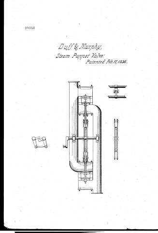
Duff and Murphy's Patent Drawing for a Manner of Raising and Depressing Puppet Valves of the Steam Engine

National Archives, Restored Patent Drawings (Record Group 241) · Full-size scan at the National Archives · Catalog record
Show the text on the drawing Hide (18 words)
Words on the drawing as machine-read by the National Archives; not checked. Useful mainly for searching.
No / (C
USPTO scan
The patent as scanned by the USPTO
-
 Page 1
-
 Page 2
-
 Page 3
-
 Page 4


U.S. Patent and Trademark Office · Google Patents
Show the transcription Hide (1,030 words)
Machine transcription (LightOnOCR) of the pages as scanned by the USPTO, most of them the handwritten copies made when the records were restored after the 1836 fire. Not checked; it can misread handwriting, so compare it with the scan.
Page 1.
9406X
Duff & Murphy,
Steam Puppet Valve.
Patented Feb. 17, 1836.
Page 2.
William Duff and Thomas Murphy
Follow Patent.
The inventors referred to in the Follow Patent and making part of the same as containing a description in the words of the said William Duff and Thomas Murphy themselves of their Improvement in the manner of raising and discharging the superficial valves of steam engines.
To all to whom these presents shall come. Be it known that we William Duff and Thomas Murphy of Baltimore in the County of Baltimore and State of Maryland have invented a new and useful improvement in the manner of raising or discharging the superficial or the steam exhausting valves in steam engines and that the following is a full and exact description of the construction and mode of operation thereof, as invented or improved by us. The object of this improvement is to place the sliding rods by which the valves of the top & bottom chests are raised or shut in a much better form of construction by which we are enabled to arrange them between the side pipes & directly beneath the top & above the lower end of so as to be able to lift or depress the strips & stems thereof by means of a perpendicular or direct line between them & through their centers instead of the present plan of placing them on the outside of the side pipes to operate on the valves by means of levers from the sides thereby projecting horizontally, or by hand gears, one set of levers being employed to each chest, as the stems of the valves are not connected, & both set of strips & levers &c. are placed in the same position, or rising a long time chest which arrangement occasions great inconvenience from the swinging and tumultuous motion attending the great length of these strips & the necessary precautions to brace against them. Our improvement consists in the following arrangement of these strips and stems so as to remedy these defects and furnish the advantages we contemplate they. The position of the valves and chests being the same as usual, we connect the top steam valve & the bottom exhausting valve by means of a long straight stem reaching from one to the other (which we call the male stem as it is to work within
Page 3.
within another hollow cone called a female stem) and that portion of it which is to work through the stuffing boxes on the female stem, placed between the top & bottom sheets we call the valve stem and is made conical. The remainder which connects these two parts may be either round or square and should so as to give strength from the centre to avoid springing, as called the rod, and is to have at each end a socket to admit the stem to be screwed into by a key, through one will have in addition a female screw into which the rod will screw so that it may be lengthened or shortened at pleasure. About the centre of this rod are two lugs on each side presenting the appearance of a square mortise with shoulders for the purpose of receiving the forked lifter from one of the cock shafts which is to be placed on one side of the side pipes directly opposite by the working of a hook with the lifter the upper and lower motion is given to the rod and stems of the valves. The life exhausting valves & the bottom steam valves are connected by means of two straps placed outside of the rod & stems just described, though still between the side pipes & fastened on to the stuffing boxes of the male valve stems by means of lugs or keys. These boxes are screwed on to the female stems as usual which work through keys on the bottom of the top sheet & of the bottom sheet. These straps are provided with two lugs on the outside of each or next to the side pipes so as to produce the connecting shoulders as are formed on the rod & stems already described as indicated between the two straps, they are taken hold of by a forked lifter from another working shaft placed on the opposite side of the side pipes to the one already described, so that by its working these straps are raised or depressed in the manner as the rod and stems, though in different directions or alternately which is provided for by connecting the rods on the working shaft by means of a rod they being both placed at the same end for that purpose and are thus made to work at the same time. The best situation for the connecting pins to communicate the motion to the shafts will be on the screw of one of them. The same principles we have explained to use when the valves or valve stems & straps are separate and made to work one by the side of the other instead of one within the other. What we claim as our invention & most with Sutton Patent for is first the arrangement of the valve stems in the top sheet in an inverted position so as to be connected by means of the rod with the stem of the valve in
Page 4.
in the lower shaft in a direct line. Secondly, The connection by means of the shafts above set forth of the stuffing box of the female stem of the lower shaft which box is also inclined so as to be thus connected in a straight line with the stuffing box of the lower shaft and finally the adaptation of the two connected working shafts as above described to produce by means of the lift-arms the alternate motion of the single stems.
Witnesses
James McHale
William Chiokeon
William Duff
Thos Murphy
1035 n.b.
Drawing
Ex.
Cf. 11.
Published accounts: journal notice
Notice in the monthly list of patents, with remarks
Journal of the Franklin Institute, new ser., vol. 18 (1836), p. 249 · View the page
65. For an improvement in the manner of raising and depressing the steam and exhaust valves of Steam Engines; William Duff and Thomas Murphey, City of Baltimore, Maryland, February 17.
Remarks. The object of this arrangement appears to be to operate upon the induction and eduction puppet valves by rods acting in a direct line. The claims are, "First, the arrangement of the valve-stem in the top-chest, in an inverted position, so as to be connected by means of the rod with the stem of the valve of the lower chest, in a direct line. Secondly, the connection by means of the straps, as set forth, of the stuffing box of the female stem of the top chest, which box is also inverted, so as to be thus connected in a straight line with a stuffing box of the lower chest; and, finally, the adaptation of the two connected rocking shafts as described, to produce by means of the lifters and lugs, the alternate motion of the stems and straps."
About this record
- Patentee
- DATAMP
- Date
- the Name and Date index of patents, DATAMP, USPTO records
- Invention
- DATAMP
- Listed in
- the Name and Date index of patents, DATAMP, USPTO records, Jim Shaw's X-patent list, the Journal of the Franklin Institute, Burke's List of Patents (1847)
- Burke's 1847 Patent Office list gives the same patent.