

Drawings and documents
National Archives restored drawings: drawing
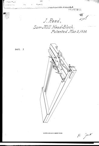
J. Reed's Patent Drawing for a Saw Mill Dog

National Archives, Restored Patent Drawings (Record Group 241) · Full-size scan at the National Archives · Catalog record
Show the text on the drawing Hide (66 words)
Words on the drawing as machine-read by the National Archives; not checked. Useful mainly for searching.
110. saws. / [130] Head Blocks. / Saw 143, MII Set SAWDIE Works, / tablets / 75d / J. REED'S / ASSITICATION / 946-0 / LIVITIONS. / Saw Mill Dog. / saw me / 9461X / Patented March 2°C 1836 / A. The long plate. / B.B. Two shoreplates. / C. The Slider / D. I've Zrever. / D'Ze Hand / E.F. Rightangle Dogs / G. The Zizzee.
USPTO scan
The patent as scanned by the USPTO
-
 Page 1
-
 Page 2
-
 Page 3
-
 Page 4
-
 Page 5


U.S. Patent and Trademark Office · Google Patents
Show the transcription Hide (1,098 words)
Machine transcription (LightOnOCR) of the pages as scanned by the USPTO, most of them the handwritten copies made when the records were restored after the 1836 fire. Not checked; it can misread handwriting, so compare it with the scan.
Page 1.
J. Reed,
Sarr-Mill Head-Block.
Patented Mar. 2, 1836.
9461 X
A.M. PHOTO-LITHO. CO. N.Y. (OSBORNE'S PROCESS)
B. Gunt
Page 2.
Mar. 2, 1836 293
Joseph Speed
Letter Patent
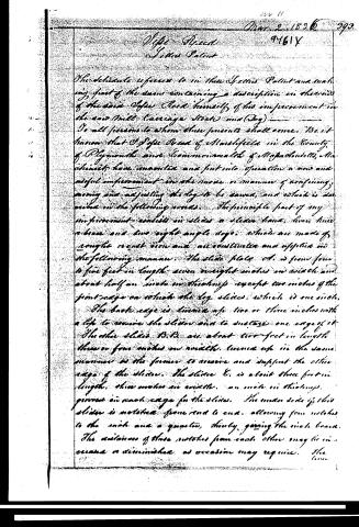
The schedule annexed to this Letters Patent and making part of the same containing a description in the words of the said Joseph Speed himself, of his improvement in the saw Mill Carriage Stock and Dog.
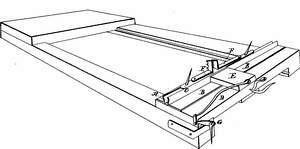
To all persons to whom these presents shall come. Be it known that Joseph Speed of Marshfield in the County of Plymouth and Commonwealth of Massachusetts, Massachusetts, have invented and put into operation a new and useful improvement in the mode or manner of confining, moving and adjusting the log to be sawed, and which is described in the following words. The principle part of my improvement consists in slides a slider head, lever, three or four and two right angle dogs, which are made of rough cast iron and are constructed and applied in the following manner. The slide plate A. is from four to five feet in length seven or eight inches in width and about half an inch in thickness except two inches of the front edge on which the log slides, which is one inch. The back edge is turned up two or three inches with a lip to receive the slider and to sustain one edge of it. The other slides B.B. are about two feet in length three or four inches in width, turned up in the same manner as the former to receive and support the other edge of the slider. The slider C. is about three feet in length, three inches in width, an inch in thickness, grooves in each edge for the slides. The under side of this slider is notched from end to end, allowing from notches to the inch and a quarter, thereby giving the inch board. The distance of these notches from each other may be increased or diminished as occasion may require. The
Page 3.
lever D, to which the hand is attached, whereby the blade is moved is about three feet in length, of width and thickness sufficient for strength. At one end of this lever is an eye of about one foot in length, two inches in diameter, and at right angles with the aforesaid lever. The other end of this eye is a crank of about three or four inches in length. The hand E, is about eight or ten inches in length, three in width, and three in thickness. In the middle of this hand is a hole, one inch and a half in diameter which is to receive one end of the crank by which said hand is suspended. This hand is made of cast iron with steel and fitted to the notches of the slide. Under this hand is a straight bail to which a weight is suspended. The legs F, G, are right angles, the horizontal part of which are sixty-two inches in length, three in width, one in thickness. The perpendicular parts are each one inch in height, two and a half inches square. In each of these are three or four holes in which wrought iron or steel teeth are fastened for supporting the log. These legs are fixed upon the slide by a swivel joint at the outer ends. Two pieces of wrought iron are fastened, one at each end of the slide, sloping back at an angle of forty-five degrees. The lever C is used for setting the log, it is constructed with a lock joint, by which the motion required is obtained, or this motion may be obtained by a second lever, about five feet in length which is placed at an angle of about forty-five degrees in a mortise in a joint which lays parallel with carriage. In the upper end of said lever is a mortise to receive one end of a circular arm about one foot in length, which is confined by a bolt. In the backward motion of the carriage the lever D comes into contact with said lever by which it is raised and the log is set.
Page 4.
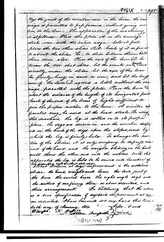
By the joint of the circular arm in the brace, the carriage is permitted to pass forward, without giving motion to the lever. The application of the machinery is as follows: Place the plate A on the carriage stock even with the inner edge, bolt it fast; place the two other slides B, D, back of it so far as to admit the slider C, to slide between them, bolt them down also. Place the axis of the lever D, between the two short slides, let the crank and hand directly under the slider, let the axis of the lever be firmly hung in wood or iron, and let the long arm of the lever D, extend a little without the carriage, parallel with the plate. Place the brace E, about the distance of the length of its horizontal part back of the end of the lever of height sufficient to give the proper motion to the lever. A similar apparatus may be used at the head stock. On using this machine, the log is rolled on to its proper place, the dogs are driven in and the circular dogs are in the back of the dogs upon the sloped iron, by which the log is firmly held. To change the motion of the slider, it is only necessary to depress one end of the hand, and the weight, sliding on the ball, will throw the other end into the motion. With this apparatus the log is held to be sawed into lumber of any proportion, with a uniform size—that is, that I claim as my improvement is the notched slider, the hand, weight and lever, the lock joint of the brace, the circular brace, the right angle dogs and the manner of connecting them as above described, and their arrangement. In testifying that the above is a true specification of my said improvement as my one described, I have hereunto set my hand this twenty day of January 1856.
Witness: H. A. B.
Filed Deced.
1856
Patent No. 1056
Drawing 2
Page 5.
Isaac Knight, Letters Patent granted, dated March 19, 1829.
Reissued tenth day of July 1834. Re. Reissued April 28, 1836. — being for Improv. in the Rail road Carriage. Recorded in volume 8, page 105 of Patent Records.
Published accounts: journal notice
Notice in the monthly list of patents
Journal of the Franklin Institute, new ser., vol. 17 (1836), p. 437 · View the page
153. Saw Mills. Isaac Reed, Mansfield, Mass.
DATAMP: illustration
Illustrations from DATAMP

DATAMP (Directory of American Tool and Machinery Patents), via the Internet Archive · Archived DATAMP page
About this record
- Patentee
- the Name and Date index of patents, Burke's List of Patents (1847)
- Date
- the Name and Date index of patents, DATAMP, USPTO records
- Invention
- DATAMP
- Listed in
- the Name and Date index of patents, DATAMP, USPTO records, Jim Shaw's X-patent list, the Journal of the Franklin Institute, Burke's List of Patents (1847)
- The name conflict was settled by Burke's 1847 list.
- The National Archives' catalog gives the name differently.
- The Franklin Institute's journal gives a different date.
- Burke's 1847 Patent Office list gives the same patent.