

Drawings and documents
National Archives restored drawings: drawing
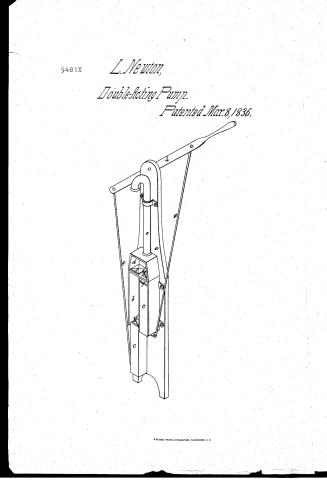
Levi Newton's Patent Drawing for a Double Force Pump

National Archives, Restored Patent Drawings (Record Group 241) · Full-size scan at the National Archives · Catalog record
Show the text on the drawing Hide (90 words)
Words on the drawing as machine-read by the National Archives; not checked. Useful mainly for searching.
C'ASS 103 PUME / ll Valved Ref frocating / Multigle Cylinder. / oton, / 11 / the gludent / CLASSIPICATION / 9481. x / DIVI TON / 9481 X / Double Hora Rumph / Patented: 8th March 1836. / References / a Standard / h Main cylinder / e Buckets / a Receiver / e Conductor / f valves. / g Pitmen / h Lever / NB. The front parts of the main- / cylinder & receiver are removed / Latent office 26, jan 1509 / Made under the direction of the team / of Intents in comfanity with cut 3.tlan 1834 / Menny Eustomath / commission fratents
USPTO scan
The patent as scanned by the USPTO
-
 Page 1
-
 Page 2
-
 Page 3


U.S. Patent and Trademark Office · Google Patents
Show the transcription Hide (622 words)
Machine transcription (LightOnOCR) of the pages as scanned by the USPTO, most of them the handwritten copies made when the records were restored after the 1836 fire. Not checked; it can misread handwriting, so compare it with the scan.
Page 1.
9481X
L. Newton,
Double-Acting Pump.
Patented Mar. 8, 1836.

Page 2.
Mar. 8, 1836
Levi Newton
Letters Patent
The Schedule referred to in these Letters Patent and making part of the same containing a description in the words of the said Levi Newton himself of his improvement in the Double force pump.
To all to whom these presents shall come, Be it known that I Levi Newton of Alexandria in the County of Genesee & State of New York have invented a new and useful improvement in making pumps denominated the Double Force Pump & that the following is a full & exact description thereof. The Double Force Pump consists of a conductor, a receiver, two cylinders or boxes, two buckets, two pistons, a standard or lever or crank & four valves. The standard may be made as this, upon the bottom of the well cistern or reservoir containing the liquid, or to rest upon the top of the same & be of any length or size required & made fast to any part thereof. The two cylinders are of any required length & diameter placed parallel in any position on the liquid and made fast therein. Or two square boxes of equal length & capacity may be substituted therefor. The receiver is of a conical form of a diameter equal to both the cylinders or boxes and placed upon the heads of the same to receive the liquid forced through them. The conductor is of any required length & shape connected with the head of the receiver to conduct the liquid to the place required & from the head of each cylinder or box & within the receiver is a valve to retain the liquid in the receiver when forced into it. The buckets are of such shape & size as to fill the cylinders & extend so far below them as to make a connection with the pistons practicable. The buckets are also hollow for the purpose of admitting the liquid through them into the receiver and have each a valve upon their head. These buckets move back & forth alternately in the cylinders and force the liquid into the receiver. The pistons are two rods attached to the feet of the buckets & connected with the lever in such manner as by the movement of the same to force the buckets up & down in the cylinders. The lever is a bar of any shape or dimension resting upon the top of the standard & is
Page 3.
2.
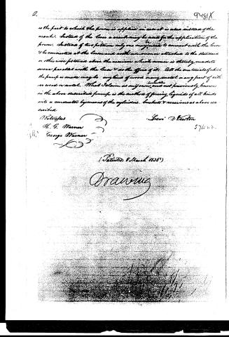
is the part to which the power is applied in case it is used instead of the crank. Instead of the lever a crank may be used for the application of the power. Instead of two pistons only one may be used to connect with the lever & be connected at the lower end with an arm or lever attached to the standard or other wise fastened above the reservoir which arm is thereby made to move parallel with the lever & do the office of it. All the materials of which the pump is made may be any kind of wood or any metal or any part of either or wood or metal. What I claim as my own, and not previously known in the above described pump is the method of forcing liquids of all kinds into a conductor by means of the cylinders, buckets & reservoirs as above described.
Testified
H. G. Warner
George Warner
Levi D. Newton
574 n 8.
(Patented 8 March 1858)
Drawing
Published accounts: journal notice
Notice in the monthly list of patents
Journal of the Franklin Institute, new ser., vol. 17 (1836), p. 438 · View the page
174. Pump, double force. Levi Newton, Alexander, N. York,
Published accounts: journal notice
Notice in the monthly list of patents, with remarks
Journal of the Franklin Institute, new ser., vol. 18 (1836), p. 321 · View the page
34. For a Double Force Pump; Levi Newton, Alexander, Genessee county, New York, March 8.
Remarks. As usual, in patents for pumps, there is nothing new in that before us. Two chambers, or cylinders, are placed in a well, and a brake carrying two piston rods, works the two pistons, and forces the water up through a common pipe.
About this record
- Patentee
- DATAMP
- Date
- the Name and Date index of patents, DATAMP, USPTO records
- Invention
- DATAMP
- Listed in
- the Name and Date index of patents, DATAMP, USPTO records, Jim Shaw's X-patent list, the Journal of the Franklin Institute, Burke's List of Patents (1847)
- Burke's 1847 Patent Office list gives the same patent.