

Drawings and documents
National Archives restored drawings: drawing
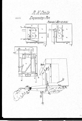
R.K. Cralle's Patent Drawing for an Apparatus for Making Salt

National Archives, Restored Patent Drawings (Record Group 241) · Full-size scan at the National Archives · Catalog record
Show the text on the drawing Hide (51 words)
Words on the drawing as machine-read by the National Archives; not checked. Useful mainly for searching.
(155) / aporating Pans. / ABU / R.K.CRALLÉ'S / 9507 X / Apparatus formaking salt. / DIVISION: / Patented March 18th 1836, / 9507X / Top. / 1. / Id / 11 / Pe / 11 / fo / 13 / on / 10 / I to / 51 / or / or / L' / I' / et / Apecture / of / Sections. / 11 / 11 / Oö / 10 / 10 / my / I' / Despective
USPTO scan
The patent as scanned by the USPTO
-
 Page 1
-
 Page 2
-
 Page 3
-
 Page 4
-
 Page 5
-
 Page 6
-
 Page 7
-
 Page 8


U.S. Patent and Trademark Office · Google Patents
Show the transcription Hide (2,892 words)
Machine transcription (LightOnOCR) of the pages as scanned by the USPTO, most of them the handwritten copies made when the records were restored after the 1836 fire. Not checked; it can misread handwriting, so compare it with the scan.
Page 1.
R. H. Crulle.
Evaporating Pan.
Patented Mar. 18, 1836.
9507X

Page 2.
9507X
Mar. 18, 1886
365.
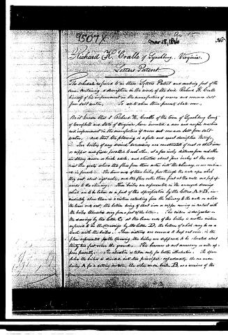
Richard H. Cralle of Lynchburg, Virginia.
Letters Patent.
The schedule referred to in these Letters Patent and making part of the same, containing a description in the words of the said Richard H. Cralle himself of his improvement in the manufacture of coarse and common salt from salt water.
To all to whom these presents shall come,
Be it known that I Richard H. Cralle of the town of Lynchburg County of Campbell and State of Virginia, have invented a new and useful machine and improvement in the manufacture of coarse and common salt from salt water, and that the following is a full and exact description thereof.
Two boilers of any desired dimensions are constructed of cast or sheet iron or copper and fixed parallel to each other, at a few inches distance from each other in strong mason or brick work, and elevated about four inches at the ends over the grates where the flues from them enter into the chimney, or are continued in funnels. The lower ends of these boilers pass through the wall upon which they rest about eight inches, and the flues enter them first at the walls and pass upwards to the chimney. These boilers are represented in the annexed drawings which are to be taken as a part of this specification by the letters A & B, immediately above them is a section extending from the chimney to the wall on which the lower ends rest; the bottom being of sheet iron or copper running in contact with the boilers themselves away from a part of the bottom. This section is designated in the drawings by the letter C; at the lower ends of the boilers is another section referred to in the drawings by the letter D, the bottom of which may be on a level with the boilers. These sections are covered to keep out rain. In the plan represented in the drawing the boilers are supposed to be elevated about thirty-two feet above the ground. This however is not necessary as will appear presently. The elevation is taken only for better illustration. The space below the boilers is divided into two principal apartments, the one under boiler A for a settling bottom, the other under boiler B, as a receiver of the
Page 3.
366. 95074
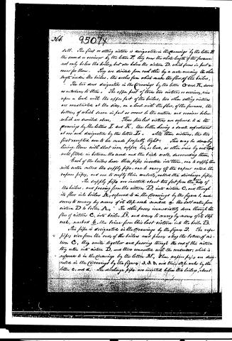
salt. The first or setting cistern is designated in the Drawings by the letter B, the second or receiver by the letter E, they run the whole length of the furnace not only below the boilers, but also below the cistern D, which forms in part a cover for them. They are divided from each other by a wall running the whole length under the boilers, the arches from which make the floor of the boilers.
The two doors designated in the Drawings by the letters G and H, serve as entrances to them. The upper part of these two cisterns or receivers, rise upon a level with the upper part of the boilers, two other setting cisterns are constructed at the sides, on a level with the floor of the furnace, the bottom of which serve in part as covers to the cistern and receiver below, which are described above. These two last cisterns are referred to in the Drawings by the letters I and K, the latter having a small expansion at one end designated by the letter L. All these cisterns, the two first excepted are to be made perfectly tight. This may be done by lining them with sheet iron, copper, tin, or lead, or other wise by red lead well filled in between the wood and the brick walls, surrounding them.
Each of the boilers have three pipes inserted into them, one to supply them with water called the supply pipe, one to carry off the vapour called the vapour pipes, and one to supply their contents, called the discharge pipes.
The supply pipes are inserted about two feet from the ends of the boilers, and passing from the cistern D, into cistern C, and through its floor into boiler A, referred to in the Drawings by the figure 1, and serves to convey by means of its stop cocks marked a the salt water from cistern D to boiler A. The other passes immediately down through the floor of cistern C, into boiler B, and serves to convey by means of its stop cocks, marked b, the brine from this last cistern into the boiler B.
This pipe is designated in the Drawings by the figure 2. The vapour pipes rise from the ends of the boilers and pass along the bottom of cistern C, they unite together and passing through the end of this cistern they enter into cistern D, and there connect with the condenser, which is referred to in the Drawings by the letter M. These vapour pipes are designated in the Drawings by the figures 3, 3, 3, and their stop cocks by the letter c, and d. The discharge pipes are inserted below the boilers, about
Page 4.
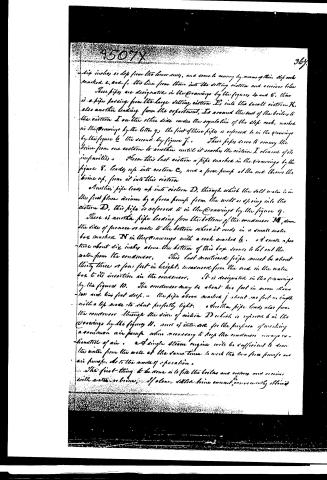
six inches or less from the lower ends, and serve to convey by means of their stop cocks marked e, and f, the lines from them into the setting cistern and receiver below. These pipes are designated in the drawings by the figures 4 and 5. There is a pipe passing from the large setting cistern E into the small cistern K, also another leading from the experiment, L, around the end of the boiler, to the cistern I on the other side under the regulation of the slip cock, marked in the drawings by the letter g. The first of these pipes is referred to in the drawings by the figure 6, the second by figure 7. These pipes serve to convey the brine from one cistern to another until it reaches the cistern I clear of its impurities. From this last cistern a pipe marked in the drawings by the figure 8, leads up into cistern C, and a force pump at the end throws the brine up, from it into this cistern.
Another pipe leads up into cistern D, through which the salt water is in the first place driven by a force pump from the well or spring into the cistern D. This pipe is referred to in the drawings by the figure 9.
There is another pipe leading from the bottom of the condenser M, down the side of furnace or well to the bottom where it ends in a small water box marked N in the drawings with a cock marked k. A small aperture about six inches above the bottom of this box serves to let out the water from the condenser. This last mentioned pipe must be about thirty-three or four feet in height, measured from the end in the water box to its insertion in the condenser. It is designated in the drawings by the figures 10. The condenser may be about two feet in mean diameter and two feet deep. The pipe above marked j about one foot in length with a lip made to shut perfectly tight. Another pipe leads also from the condenser through the side of cistern D which is referred to in the drawings by the figure 11, and is intended for the purpose of working a common air pump when necessary to keep the condenser always exempt of air. A single steam engine will be sufficient to draw the water from the well at the same time to work the two force pumps and air pumps. As to the mode of operation.
The first thing to be done is to fill the boilers and cisterns and receivers with water or brine. If clean salted brine cannot conveniently obtained
Page 5.
for this purpose, common spring water or other unimpregnated water will answer the purpose—it being advisable not to use the salt water which has not been salted after boiling, unless indeed the salt water be free of impurities such as petroleum and the oxygen of air, which is not the case with that which I use. So this cold water from a spring or river may be thrown by the force pump up the pipe marked g into cistern D, from thence it will pass down into boiler A, through the pipe marked l, thence into the large cistern E, and through the cistern K, to cistern I, from thence by the force pump it is raised through the pipe 8, into cistern C, and passing through the stop cock marked b, into boiler B, it descends into the large receiver F and fills that. Thus all the cisterns as well as the boilers are filled with water or brine. When this is effected the next step is to exhaust the condenser, M, and to obtain a vacuum. To this end let the stop cocks of the supply pipes, the vapour pipe, and the discharge pipe be closed, close also the stop cock of the long pipe leading from the condenser, to the water box outside the wall or furnace. Then opening the top of the short pipe leading from the top of the condenser marked j, fill the condenser and its annexed pipes full of water from the cistern D continue to pour in water until it runs over at the top of the short pipe marked j, this being done close up the top of the short pipe j, perfectly tight, and open the stop cocks in the water box marked h, the water in the condenser and its pipes will sink down to about thirty-two feet above the level in the water box. The pressure of the air from without being equal to the weight of a column of water of that height.
In this way the condenser will be an exhausted receiver, and the air pump being put in operation will preserve it so. You may now open the stop cocks of the vapour pipes, and build up the fire under the boilers, the door opening on the grate being designated in the drawings by the letter O, and the chimney by the letter P. The column of water in the vapour pipes will not be sufficient to arrange the boilers or cisterns, or if any danger be apprehensive, it may be assisted by a safety valve on the boilers or cisterns. When the water begins to boil the vapour will rise through the pipes into the condenser, which being kept cold by the descending water will condense, it immediately and it will pass down the long pipe into the water box, and from thence out through the aperture. The steam from which regulates the quantity to be admitted into the
Page 6.
boiler through the supply pipe, the stop cock of which, ought not to be opened until about one-third of the water in the boiler is evaporated; and time only in such proportion as not to increase the amount. A gauge to this may be fixed in various ways. A strong glass glass tube inserted in the upper ends of the cistern B and the receiver E, on a level with the desired height of the water in the boiler would serve the purpose. But no especial particularity is necessary.
Practice and attention to the state of the fire, and the stream of water from the water box will soon render the regulator of but little use. Upon this plan then it will be seen that the salt water is first conveyed into the cistern D, whence it is conveyed into the boiler A, where it is condensed and passing into the settling cisterns deposits its impurities, and comes into the last settling cistern I. (the cisterns if necessary may be increased in number.) thence it passes into cistern C, and from that into the boiler B, where it is brought into such a condensed state as to begin to form into chrysolite. From this it goes into the receiver F where the chrysolite while continually forms and falls to the bottom, displacing the water or brine gradually which rises into the boiler when the receiver is full. The stop cock of the discharge pipe, is closed, and often opening the cock in the receiver marked in the Drawings by the letter F in order to let off the bitter water &c the door may be opened and the contents removed into the salt house.
The door in the large cistern E, is for the purpose of cleaning and cleaning it when necessary. The receiver F ought to be made very large, so as that the furnace might not blow out sooner than once a fortnight or longer. By this mode of manufacture there is a saving in fuel, a greater saving still in repair and breaking of pans, and bottles, and the salt is almost if not entirely free of all impurities. I have observed that the plan represented in the Drawings supposes an elevation of the boilers about thirty feet above the surface. This is for convenience in the model and the drawings. It is by no means necessary or desirable to so construct a furnace unless under circumstances which only rarely exist. What might seem to recommend it, is that it removes the difficulty of overcoming the elevation requisite for the pipe an upper to the condenser. Were the boilers near the surface, and the vapour pipes elevated to the height of thirty feet, together with one of the supply pipes, when filled with water, the weight of the column would burst both both boilers & cisterns.
Page 7.
if the stop cocks were opened, and they previously filled with water, even this difficulty however is readily obviated. The vapour pipes might be extended in a straight line above the boiler to the height of thirty two feet passing over the condenser, and reaching to the elevation of the short pipe above, being connected with the condenser by an elbow or stop cock, and left open at top.
After the boiler and cisterns as filled as before, the stop cocks of the vapour pipes and supply pipe above a piston with a valve and elbow sliding box might be passed down the pipes to the stop cocks, and the pipes being filled with water up to the top as well as the condenser and its annexed pipe, the vacuum might be produced in all at the same time, by closing the top of the short pipe above the condenser, and opening the stop cocks, in the water box as before, and at the same time drawing up the pistons in the vapour pipes, by pulling, until the sliding boxes passed the elbow or valve when they are connected with the condenser. In this way the water from the vapour pipe would pass from them into the condenser, and down the pipe into the water box, and the tops of all being shut up close the vapour pipes as well as the condenser would be exhausted occasion; and the cocks being open below the fire might be kindled immediately. This would be the best mode where the fuel was to be raised from below, and the ground would not allow of another and more convenient mode.
But where the surface is hilly, the best site is on the side or top of a hill, where no difficulty presents itself. The long pipe from the condenser is in such case carried down the hill to the necessary depth. Or in a level country it may be sunk in a well dug for the purpose, or conducted under ground to such a distance as may be necessary to produce the desired fall. In all these cases (and it can very rarely happen, that the plan in the drawing represented would be most acceptable) the cistern and receiver described as beneath the boiler may be either in front or in the rear, or at the sides as the builder above. The plan in the drawing as I have said only for convenience, and to illustrate the application of the principle. The thing most necessary to be observed by the builder is to have all the settling cisterns and receivers perfectly tight and strong whether he elevates his boiler or not. What I claim as my own invention
Page 8.
not heretofore known or used, in the above described machine is the application of the principle of evaporation in vacuo to the manufacture of coarse and common salt. I claim to have invented the means of applying a known principle in physics to the new and useful purpose of salt-making. The machine described so far as its construction is peculiar to the purpose above, I claim to be my own invention. The machine may be varied in its construction and the principle applied in other modes, but I claim to be the original inventor of the means of applying the principle of evaporation in vacuo to the manufacture of coarse and common salt.
Witnesses:
H. P. Elliot
B. H. Morrell
Richard H. Craville.
3045
Drawing
Published accounts: journal notice
Notice in the monthly list of patents, with remarks
Journal of the Franklin Institute, new ser., vol. 18 (1836), p. 389 · View the page
67. For Manufacturing Salt from salt water; Richard K. Cralle, Lynchburg, Campbell county, Virginia, March 18.
Remarks. A very ery full description of the apparatus employed is given in the specification, after which the patentee says, "What I claim as my own invention, not heretofore known or used, in the above described machine, is the application of the principle of evaporation in vacuo, to the manufacture of coarse and common salt. I claim to have invented the means of applying a known principle in physics, to the new and useful purpose of salt making. The machine described, so far as its construction is peculiar to the purpose above, I claim as my own invention. The machine may be varied in construction, and the principle applied in other modes; but I claim to be the original inventor of the means of applying the principle of evaporation in vacuo, to the manufacture of coarse and common salt." The apparatus, as shown in the drawings, is intended merely to exemplify the principle, and not to furnish a definite arrangement; the description of it is elaborate and clear, but we find nothing to designate in what "its construction is peculiar to the purpose;" and therefore cannot tell what is claimed; this ought to have been distinctly set forth, as, in our opinion, it would form the only foundation for a valid claim. It has been decided that the application of a known machine to a new purpose is not patentable. To apply the same mode to the evaporation of water from a solution of salt, which has been applied so extensively to its evaporation from a solution of sugar, cannot fairly be called an invention, however useful it may be. If geese had never been roasted, although turkies had been usually cooked in that way, a patent for roasting geese would hardly be sustainable.
Published accounts: journal notice
Notice in the monthly list of patents (listed with a different spelling or date)
Journal of the Franklin Institute, new ser., vol. 17 (1836), p. 438 · View the page
Salt, making.-Richard K. Crallé, Lynchburg, Va.
About this record
- Patentee
- DATAMP
- Date
- the Name and Date index of patents, DATAMP, USPTO records
- Invention
- DATAMP
- Listed in
- the Name and Date index of patents, DATAMP, USPTO records, Jim Shaw's X-patent list, the Journal of the Franklin Institute, the Journal of the Franklin Institute, Journal, Burke's List of Patents (1847)
- Also listed in a contemporary journal or list under a different spelling or date; the record shown follows the standard lists.
- Burke's 1847 Patent Office list gives the same patent.