

Drawings and documents
USPTO scan
The patent as scanned by the USPTO
-
 Page 1
-
 Page 2
-
 Page 3
-
 Page 4
-
 Page 5
-
 Page 6
-
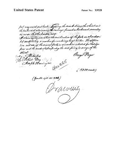 Page 7


U.S. Patent and Trademark Office · Google Patents
Show the transcription Hide (2,251 words)
Machine transcription (LightOnOCR) of the pages as scanned by the USPTO, most of them the handwritten copies made when the records were restored after the 1836 fire. Not checked; it can misread handwriting, so compare it with the scan.
Page 2.
United States Patent
Patent No.: X9528
George Page of Keene, New Hampshire
Letters Patent
The Schedule referred to in these Letters Patent and making part of these now containing a description in the words of the said George Page himself of his improvement in the machine for mortising Large Timber.
Be it known that I George Page of Keene in the County of Cheshire and State of New Hampshire have invented a new and useful machine for making mortises in large timber, and that the following is a full and exact description of the construction and operation of said machine as invented by me. The exterior part of the machine is a cast iron Box open at top and bottom, about two feet long and seven inches wide. The sides and ends are cast separately and fastened together by screws passing through the ends into ears on the inside of the side pieces. Ears also project two from each side quite at the end and bottom of the box on the outside through which is cut a female screw. Underneath each end of the box and under the ears last described is placed a bar of iron about eleven inches long one and a half inch wide and one inch thick, through each end of which a hole is drilled to receive a round screw on the end of the screw which passes through the ears above. These holes are countersunk on the lower side and the end of the screws headed. The bars rest upon the timber to be mortised and by turning the screws the box can be raised or lowered and thus the depth of the mortise may be regulated, and by turning one or more of the screws of the machine may be levelled or squared with the plumb spots. At the bottom of the end pieces inside, at or near the center, ears project thro' which a hole is made and a hole is also made thro' the bars above mentioned, in and through which is inserted an iron guide which is made fast to the box, the sharpened end of which enters the timber and keeps the machine in its place. The sides of the box are about three eighths of an inch thick but at the lower edge on the inside is a rib to give the sides greater strength.
Page 3.
United States Patent
Patent No.: X9528
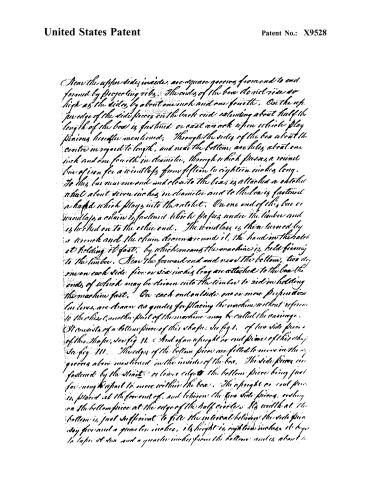
Near the upper side inside are square grooves from end to end formed by projecting ribs. The ends of the box do not rise so high as the sides by about one inch and one fourth. On the upper edge of the side pieces on the back end extending about half the length of the box is fastened or cast an arch upon which play pinions hereafter mentioned. Through the sides of the box about the centre in regard to length, and near the bottom, are holes about one inch and one fourth in diameter, through which passes a round bar of iron for a windlass from fifteen to eighteen inches long. To this bar near one end and close to the box is attached aatchet wheel about seven inches in diameter and to the box is fastened a haphed which plays into theatchet. On one end of this bar or windlass a chain is fastened which passes under the timber and is hooked on to the other end. The windlass is then turned by a wrench and the chain drawn around it, the hand on theatchet holding it fast, by which means the machine is held firmly to the timber. Near the forward end and near the bottom, two pieces on each side five or six inches long are attached to the box, the ends of which may be driven into the timber to aid in holding the machine fast. On each end outside one or more perpendicular bar lines are drawn as guides for placing the machine without reference to the timber, another part of the machine may be called the carriage.
It consists of a bottom piece of this shape, see fig. 1, of two side pieces of this shape, see fig. 11, and of an upright or end piece of this shape, see fig. 111. The edges of the bottom piece are fitted to move in the grooves above mentioned in the inside of the box. The side pieces are fastened by the struts or lower edges the bottom piece being just far enough to part to move within the box. The upright or end piece is placed at the forward end, and between the two side pieces, resting on the bottom piece at the edge of the half circle. Its width at the bottom is just sufficient to fill the interval between the side pieces, say five and a quarter inches, its height is eight and a half inches, it begins to taper at six and a quarter inches from the bottom and is about 1.
Page 4.
United States Patent
Patent No.: X9528
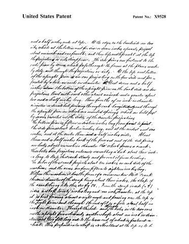
and a half inches wide at top. At the edges on the backside are two ribs which at the bottom and for six or seven inches upwards project about one inch and one fourth, and then taper and disappear until at the top the projections or ribs disappear. The side pieces are fastened to the end piece by screws which pass through the former at the places marked by dots, and through the projections or ribs. At the top and bottom of the upright piece is an ear projecting on the four sides and fastened by a hole one inch in diameter. About seven and a half inches above the bottom of the upright piece on the back side are two projections, each with each other about an inch and a quarter apart and a half inch long. Three fourths of an inch in diameter is a small hole passing through each longitudinally and through the upright piece in which are inserted springs which are held fast by screws inserted in the sides of the circular projections.
The bottom piece is fifteen or sixteen inches long from front to point. The side pieces are twelve inches long, and at the widest end six inches, and at the center three and a half inches wide. About three and a half inches back of the forward end of the side pieces are holes about one inch in diameter, that which passes a crank. These holes have projections outwardly resembling a hub about three inches long to keep the crank steady and prevent it from bending. The hub of this crank projects about ten inches on each side of the machine, and the arms are from fifteen to eighteen inches long.
Within the machine it has the form of a common two Mill crank. The same diameter of the screw being about three inches, the shape of the crank being like this see fig IV. From the screw inside (o t) rises a shaft twenty inches long and one inch diameter, at the top it is bent forming almost a right angle and passing over the top of the upright piece and through the end of it is a hole about half an inch in diameter. Through this hole and the holes in the two ears on the upright piece extends another shaft about one inch in diameter and two feet long and to the lower end of which is fastened a crank. This projection on shaft is so shouldered at the top as to be
Page 5.
United States Patent
Patent No.: X9528
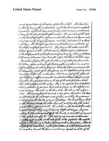
*revolved up and down by the action of the other shaft. The chain is revolved by turning the crank which may be turned round or a flat way round, and back as is most convenient, or as is rendered necessary by the desired depth of the motion. On one side of the last mentioned shaft a piece of iron one fourth of an inch square and about six inches long is fastened, and also just above it a knob or button. The two springs above mentioned are on each side of the shaft and press against it. They have on the sides near the shaft a square notch, which receives the piece of iron fastened to the shaft, and it is then prevented from turning. It may be turned half round, so however it is desirable to face the chain the other way.
An arbor passes through the other end of each side piece near the bottom, upon each end of which is a pinion about one and a half inch diameter which plays in the teeth of the above mentioned. On the same arbor inside of the side pieces, are two ratchet wheels, about four and a half inches in diameter. And to one end of this arbor on the side the pinion is fixed a small crank about three inches forward of this arbor, through projections on the top of the side pieces are holes, through which passes another arbor. This arbor opposite to each ratchet wheel is attached by means a hand wheel which plays in the ratchet, one screw entering the arbor on the lower side, the other on the upper side. The screws project an inch or two from the arbor, the hands are attached to the outward ends of them, and they being so curved inward, give the hands more or less play. One hand has a hook on the end and so any, the other has not and pushes the wheel round that is opposite to it. The notches in the two ratchet wheels being cut so that they may be turned different ways, to give motion to the arbor and play to the hands, a small groove is made in this shaft see fig V. The end (a) is inverted in the arbor near the end inside on the side of the arbor opposite the ratchet wheel. At (b) is a leaden ball an inch in diameter. Into the shaft of the crank (c) a flat pin is screwed and when the crank is turned the pin is coming against one side of the
Page 6.
United States Patent
Patent No.: X9528
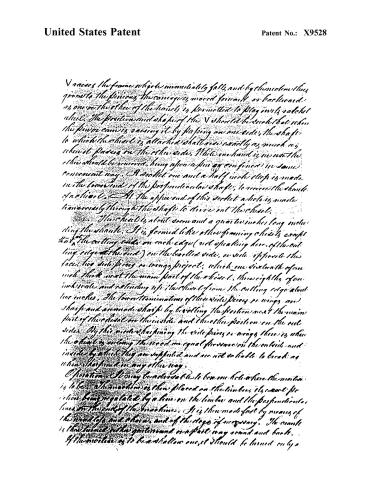
V raises the frame which immediately falls and by them the thing given to the pivoting the cam goes, moved forward or backward as one or the other of the hands is permitted to play in its selected wheel. The position and shape of the V should be such that when the pivot cam is raising it by flapping on one side, the shaft to which the wheel is attached shall rise exactly as much as when it passes on the other side. While one hand is used the other should be moved, being often a pin or confined in some convenient way. A socket one and a half inch deep is made in the lower end of the perpendicular shaft, to receive the shaft of a wheel. At the upper end of this socket a hole is made transversely through the shaft to drive out the wheel.
The wheel is about seven and a quarter inches long including the shaft. It is formed like other framing wheels except that the cutting edge on each edge (not speaking here of the cutting edge at the end) on the beveled side, on side opposite the face, two side pieces or wings project, which are sixteenth of an inch thick most the main part of the wheel, three eighths of an inch wide and extending up the shaft from the cutting edge about two inches. The lower terminations of these side pieces or wings are sharp and are made sharp by beveling the portion near the main part of the wheel on the inside and the other portion on the outside. By this mode sharpening the side pieces or wings there is when the wheel is cutting the wood an equal pressure on the outside and inside by which they are supported and are not so liable to break as when sharpened in any other way.
Operation: It may be advisable to bore one hole where the motion is to be. The machine is then placed on the timber, the exact position being regulated by a line on the timber and the perpendicular lines on the ends of the machine. It is then made fast by means of the wood legs and chains, and of the stops if necessary. The crank is then turned either gentleman or a part way round and back. If the motion is to be a shallow one, it should be turned only a
Page 7.
United States Patent
Patent No.: X9528
pat may go and put back. Turning the crank drives the chisel into the timber and also moves the carriage forward or backward, according as move the other hand, etc.
I claim as my invention the combination of the parts as described, said constituting a machine for working large timber. The application and use of the several parts in a machine intended for that purpose and the mode of sharpening the side pieces or wings of the chisel.
George Page
5-2-9 Witness
1/6 Schiel Day
Joseph Harrington
Spec 225
(22.10 words)
(Granted April 21, 1886)
Drawing
About this record
- Patentee
- DATAMP
- Date
- DATAMP, USPTO records
- Invention
- DATAMP
- Listed in
- the Name and Date index of patents, DATAMP, USPTO records, Jim Shaw's X-patent list, Burke's List of Patents (1847)
- The sources give the patentee's name differently; the name shown follows DATAMP and Shaw.
- The sources give different dates; the date shown is the one most of them agree on.
- Burke's 1847 Patent Office list gives the same patent.