

Drawings and documents
USPTO scan
The patent as scanned by the USPTO
-
 Page 1
-
 Page 2
-
 Page 3
-
 Page 4
-
 Page 5


U.S. Patent and Trademark Office · Google Patents
Show the transcription Hide (1,436 words)
Machine transcription (LightOnOCR) of the pages as scanned by the USPTO, most of them the handwritten copies made when the records were restored after the 1836 fire. Not checked; it can misread handwriting, so compare it with the scan.
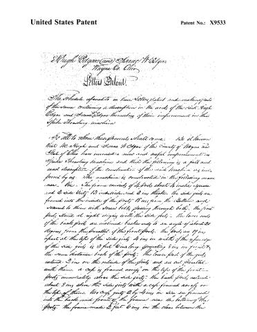
Page 2.
United States Patent
Patent No.: X9533
Hugh Edgar (and) Isaac Edgar
Wayne Co. Ohio
Letters Patent
The Schedule referred to in these Letters Patent and making part of the same containing a description in the words of the said Hugh Edgar and Isaac Edgar themselves of their improvement in the Spoke Thrashing machine.
To all to whom these presents shall come: We do hereby declare that we Hugh and Isaac Edgar of the County of Wayne and State of Ohio have invented a new and useful improvement in Spoke Thrashing Machines, and that the following is a full and exact description of the construction of the said Machine as improved by us. The machine is constructed in the following manner — The frame consists of 4 posts about 4 inches square and 2 side girts 13 inches wide and 2 ins thick. The side girts are framed into the inside of the posts 18 ins from the Bottom and secured to them with screw bolts passing through both. The front posts stand at right angles with the side girts. The lower ends of the back posts are inclined backwards to an angle of about 20 degrees from the parallel of the front posts. The posts are 19 ins apart at the tops of the side girts 4 ins in width of the upper edge of the side girts is 3 feet 6 ins long projecting 8 ins in front & the same distance back of the posts. The lower part of the girts extend 2 ins on the outside of the posts and are cut parallel with them. A cap is framed across on the top of the front posts immediately above the side girts. The back posts extend about 8 ins above the side girts with a cap framed across on the top of them. Two cross girts 2 by 4 ins in size are framed into the back and front of the frame near the bottom of the posts. The frame made 2 feet 6 ins in the clear between the
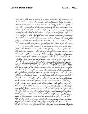
Page 3.
United States Patent
Patent No.: X9533
Side girts — The concave consists of 2 pieces 2 feet 6 ins long and 28 ½ ins thick. The lower piece 3 ins wide on the upper side which is made concave and forms an arc of a circle. The radius of which is 9 ¾ ins. The concave part of the upper piece is of the same dimensions and shape as the lower piece. The back part is made wide enough to extend nearly to the back of the frame. It is made the proper slope and used as part of the feed apron. The concave commences immediately under the center of the cylinder and inclines toward the back of the frame. The concave is supported at each end in a rabbet formed on the inside of the side girts, by cutting inch board to fit the upper and under sides of the concave and making them fast to the side girts. The concave contains about 28 spikes made and placed in the following manner. That part of the spacing which extends above the surface of the concave is 18 ½ ins long 5 ⅜ of an inch square at the surface of the wood and ¾ of an inch square at the point. Stopping them equal on the 2 sides and making the slope all on the back side to bring them to the shape above described. Leaving the thickness of wood in the same manner in a suitable manner to form the front side the front side straight. A one full row of 17 spikes 3 ½ placed near the lower edge of the lower concave piece an equal distance apart. Another half row is placed near the upper edge of the same piece. The spikes in the half row are placed exactly above the alternate spikes in the lower row. 2 half rows like the one just described are placed in the upper piece. The spikes in each row placed so as to stand above the spaces in the row next below. Both pieces of the concave are covered with Sheet Iron. An apron extends from the lower part of the concave in a horizontal direction to the front end of the girts and rests on a board which fills the space between the above apron and the roof girt below and answers for a brace to the frame. The lower end of the feed apron joins the upper edge of the concave and rests on a small tie frame into the top of the side girts near the back end an inch board is placed on the front end of the side girts and fills the space between the front edge and the end of the side girts and prevents the grain
Page 4.
United States Patent
Patent No.: X9533
from rising too high as it passes out of the machine. Hemicircular pieces are placed on the side girts between the posts and cut to a curve of 10 in. radius from the center of the cylinder. That part of this curve between the girts is covered with sheet iron which forms a cup over the cylinder. The cylinder shaft is made of 18 1/2 in. square bar iron 3 feet 11 in. long, with 2 journals 30 in. apart, and 6 in. to project on the outside of the journal at one end to receive the pulley. The journals each 2 in. long and 1 1/4 in. diameter. These journals run in boxes of cast iron or some other suitable material placed in the top of the side girts in the center between the front and back posts on the shaft and between the journals are placed 3 heads, 13 in. diameter and 18 1/2 in. thick, one in the center and one at each end near the journals. The heads are put on the shaft with cast iron centers made with flanges which are riveted to the head. On the surface of the heads and lengthwise of the cylinder are placed six pieces of lagging 24 1/2 in. long. The width of the surface of each piece is 1/2 part of the circumference of the head, they are 2 in. thick and let the whole thickness into the heads. In each piece of lagging there are 10 splices in a half row so that each 2 pieces constitute a whole row. The splices in one row following the spaces in the other so as to fill the spaces in the lower row of the concave. That part of the cylinder splices which extend beyond the surface of the lagging are the same length and shape of the splices in the concave. The sloped side of the splices are set to run foremost as the cylinder revolves. The other end is 2 1/2 in. inches long, made tapering with a screw cut on the end to receive a burr. The splices are put through the lagging and the burr screwed on the inside to prevent the splices from being thrown out by centrifugal force and to make it convenient to replace splices which may be injured or broken by accident. The lagging is covered with sheet iron. The ends of the cylinder are secured with sufficient
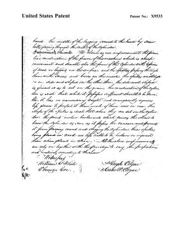
Page 5.
United States Patent
Patent No.: X9533
bands. The middle of the lapping seemed to the head by screw bolts passing through the centre of the cylinder.
Improvements claimed. We claim as our improvement to the piece, the construction of the frame of this machine which is cheap, convenient and durable also the form of the cylinder with copies of wood or lapping on the surface, and the spikes passing through them with screws and brims on the inside. The spikes are straight on one side and sloped on the other three. The side most sloped is placed so as to act on the grain. The construction of the cylinder is such that while it possesses sufficient strength to be durable, it has no unnecessary weight and consequently requires less power to propel it than most of those now in use. The shape of the spikes is such that when they are set in the cylinder, the points incline backwards which causes the straw to leave the cylinder as soon as it passes the concave and prevents it from passing round and clogging the cylinder. These spikes being placed in wood are less liable to be broken or injured than when placed in iron. All the above improvements we rely on together with the privilege to vary the proportions and materials according to the Law.
Witnesses
William S. White
Abner J. Coe
Hugh Cigar
Isaac M. Cigar
Published accounts: journal notice
Notice in the monthly list of patents
Journal of the Franklin Institute, new ser., vol. 17 (1836), p. 439 · View the page
233. Thrashing machine.-Hugh and Isaac W. Edgar, Wayne co. Ohio,
About this record
- Patentee
- DATAMP
- Date
- the Name and Date index of patents, DATAMP, USPTO records
- Invention
- DATAMP
- Listed in
- the Name and Date index of patents, DATAMP, USPTO records, Jim Shaw's X-patent list, the Journal of the Franklin Institute, Burke's List of Patents (1847)
- Burke's 1847 Patent Office list gives the same patent.