

Drawings and documents
National Archives restored drawings: drawing
E.M. Shaw's Patent Drawing for a Mortising Machine

National Archives, Restored Patent Drawings (Record Group 241) · Full-size scan at the National Archives · Catalog record
Show the text on the drawing Hide (39 words)
Words on the drawing as machine-read by the National Archives; not checked. Useful mainly for searching.
144. WOOD WORKING MACHINES. / Mortising, Chisel Cutters. / #1- / classinication / 9.537 x / DIVISION / 9537X / Mortising machine / Potented 23 march1236. / Williabram sape / Andview / rut / Trop View / 530 / 11 / In / of
USPTO scan
The patent as scanned by the USPTO
-
 Page 1
-
 Page 2
-
 Page 3


U.S. Patent and Trademark Office · Google Patents
Show the transcription Hide (816 words)
Machine transcription (LightOnOCR) of the pages as scanned by the USPTO, most of them the handwritten copies made when the records were restored after the 1836 fire. Not checked; it can misread handwriting, so compare it with the scan.
Page 1.
9537X
E. M. Sharr,
Mortising Machine.
Patented Mar. 23, 1836.

AM. PHOTO-LITH'Y. CO. N. Y. (OSBORNE'S PROCESS)
Page 2.
9537x
Mar 23, 1836
Crastus A. Shaw of Wilbraham, Massachusetts
Letters Patent.
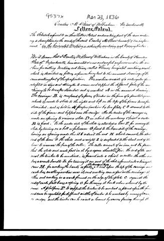
The Schedule referred to in these Letters Patent and making part of the same containing a description in the words of the said Crastus A. Shaw himself of his improvement "in the horizontal Mortising machine for mortising and tenoning timber."
Be it known that S. Crastus M. Shaw of Wilbraham in the County of Hamilton State of Massachusetts, have invented a new and useful improvement in the machine for cutting Mortises and tenons called "Shaw's horizontal mortising machine," which is described as follows referring being had to the annexed drawings of the same making part of these specifications. This machine consists of a rectangular frame adapted in size and strength to receive and support the different parts of the machine to be hereafter described and is marked A in the annexed drawing. The carriage B is composed of a piece of timber in the form of a parallelogram which is made to slide to the right and left on the top of the frame hereafter described, and is held in its proper position by two plates C C screwed to the side of the frame and lapped over the carriage. In the center of the carriage is made an opening to receive a slide D in which the mortising chisel or cutter E is fixed. To the under side of the slide is attached a lever F for moving the slide by turning on a bolt or fulcrum G fixed to the lower side of the carriage, having an opening made through it to admit the rod H which connects the short end of the lever to the slide and a weight I is suspended to the short end of the lever to increase the force of the cutter. The cutter consists of an iron rod K passing through the slide and made fast in it by a square shoulder pin. The end of the rod near the timber to be mortised, is formed into a chisel or cutter, the other end has a crank handle L, for turning it on and if the slide is formed into a triangular cam M, for working the handle or pallet, the cam is placed upon the top of the carriage and each has an oblong notch near its end resting over a pin in the carriage, the other end working in a notch formed on the edge of the plate C against the end of each pallet being a spring O for throwing it back when relieved by the cam. A platform P to support the timber to be mortised is placed upon the frame and can be regulated for different widths of timber to be mortised by means of screws or wedges, and the timber can be raised or lowered by screws passing through it.
Page 3.
9537X
Mar 23, 1836
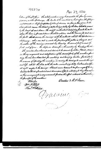
bottom of this platform. The whole machine may be secured to the floor by means of screws or other fastenings. The timber to be mortised is laid upon the platform and secured in its proper position by clamps or screws, on which is then given to the slide which causes the chisel or cutter horizontally by the lever which is moved by the hand up and down. The weight on the short end giving force to the cutter when the lever is pressed down the slide rotates and the cannon its end with the pull which moves the carriage with the cutter &c whilst the timber remains stationary. When one cut is made the position of the cutter is changed, and the motion of the carriage reversed by throwing the second pull in and the first out of gear. The chips are drawn from the mortise by feeding the chip.
The invention here claimed and desired to be secured by Letters Patent, consists in the arrangement and adaptation of the several parts of the machine producing the one here described for mortising and tenoning timber, particularly the manner of operating the machine in causing the carriage to move to the right and left, whilst the slide with the cutter moves horizontally backwards and forwards at right angles to the carriage. I do not mean however to confine myself to any particular kind of material and dimensions of parts, intending to vary these as well as their arrangement in any manner to produce the effect intended without changing the principle of the machine.
Witnesses
Wm. P. Elliot
Thos. P. Stotting
Gracilis M. Shaw
Patented 1836
Published accounts: journal notice
Notice in the monthly list of patents
Journal of the Franklin Institute, new ser., vol. 17 (1836), p. 439 · View the page
230. Mortising machine. Erastus M. Shaw, Wilbraham, Mass.
DATAMP: illustration
Illustrations from DATAMP


DATAMP (Directory of American Tool and Machinery Patents), via the Internet Archive · Archived DATAMP page
About this record
- Patentee
- DATAMP
- Date
- the Name and Date index of patents, DATAMP, USPTO records
- Invention
- DATAMP
- Listed in
- the Name and Date index of patents, DATAMP, USPTO records, Jim Shaw's X-patent list, the Journal of the Franklin Institute, Burke's List of Patents (1847)
- The Franklin Institute's journal spells the name differently.
- Burke's 1847 Patent Office list gives the same patent.