

Drawings and documents
National Archives restored drawings: drawing
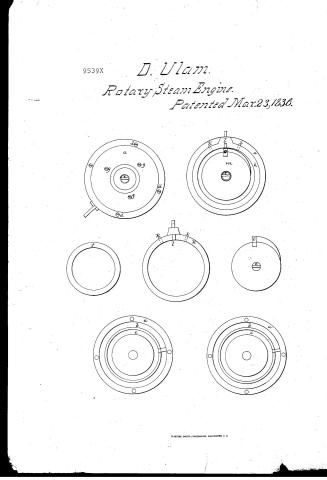
David Ulam's Patent Drawing for a Rotary Steam Engine

National Archives, Restored Patent Drawings (Record Group 241) · Full-size scan at the National Archives · Catalog record
Show the text on the drawing Hide (23 words)
Words on the drawing as machine-read by the National Archives; not checked. Useful mainly for searching.
T10 / ou / the / 20 / 36 / of / De / of / each / 224 / 20
USPTO scan
The patent as scanned by the USPTO
-
 Page 1
-
 Page 2
-
 Page 3


U.S. Patent and Trademark Office · Google Patents
Show the transcription Hide (748 words)
Machine transcription (LightOnOCR) of the pages as scanned by the USPTO, most of them the handwritten copies made when the records were restored after the 1836 fire. Not checked; it can misread handwriting, so compare it with the scan.
Page 1.
9539X
D. Ulam
Rotary Steam Engine.
Patented Mar. 23, 1836.

Page 2.
9539X 3-23-1836
David Ilam of Greensburg, Pennsylvania
Letters Patent
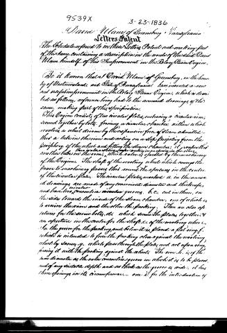
The Schedule referred to in these Letters Patent and making part of the same, containing a description in the words of the said David Ilam himself, of his Improvement in the Rotary Steam Engine.
Be it known that I David Ilam of Greensburg, in the county of Westmoreland and State of Pennsylvania, have invented a new and useful improvement in the Rotary Steam Engine, which is described as follows, reference being had to the annexed drawings of the same, making part of this specification.
This Engine consists of two circular plates, embracing a circular rim, secured together by bolts, forming a circular chamber within which revolves a wheel driven by the expansive force of steam admitted into a tube in the rim and acting on a stop projecting from the periphery of the wheel and filling the steam chamber; it wraps the two plates, a sliding valve working in an opening in the rim, and the tube in the rim, which valve is operated by the machinery of the Engine. The shaft of the revolving wheel which conveys the power to machinery passes thru round the aperture in the centre of the circular plate. The circular plates, marked a, in the annexed drawings, are made of any convenient diameter and thickness, and have two concentric circular grooves, b c, cut in them, on the sides towards the inside of the steam chamber, one of which is to receive the rim and the other the packing. There are also apertures for the same bolts, d, which secure the plates together; and an aperture in the centre for the shaft, e, of the revolving wheel. In the groove for the packing and below it is placed a flat ring f, which is intended to force the packing close against the revolving wheel by means g, which pass through the plates and act upon ring, forcing it with the packing against the wheel. The rim h, is of the same diameter as the outer concentric groove in which it is to be placed, and of any suitable depth and as thick as the groove is wide. It has three openings in its circumference, one i, for the introduction of
Page 3.
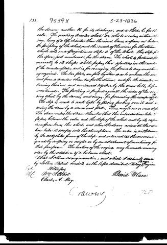
the steam, another, R, for its discharge, and a third, C, for the valve. The revolving circular wheel, m, which revolves within the rim, being of a less diameter than the rim, leaves a space, n, between the periphery of the wheel and the inside of the rim, for the steam which acts on a projection or stop, o, of the wheel. This stop fills the space just mentioned, for the steam. The wheel is fastened permanently to its shaft, which passes through apertures in the center of the circular plates, and is for conveying the force to any machinery as required. The two plates are put together so as to embrace the rim, and form a circular chamber for the steam, and for the circular wheel turning therein, and are secured together by the screw-bolts before mentioned. The packing is placed against the sides of the revolving wheel by the screw and rings, for preventing the escape of the steam.
The stop is made to work light by placing packing over it and securing the same by a screw and plate. There may be one or more stops. The steam enters the steam chamber through the introduction tube, d, passes between the valve and the stop of the wheel and by its expansive force turns the wheel, and when the steam arrives at the discharge tube it escapes into the atmosphere. The valve is actuated by the wedge-like form of the stop and released at the moment required by a spring or weight or by an attachment of machinery for that purpose. The motion of the engine may be made more regular by the addition of a balance wheel.
What I claim as my invention, and which I desire to secure by Letters Patent consists in the before described Rotary Engine.
Witnesses
M. J. Elliot
Charles A. May.
David M. Mann.
Published accounts: journal notice
Notice in the monthly list of patents
Journal of the Franklin Institute, new ser., vol. 17 (1836), p. 439 · View the page
234. Rotary steam engine. David Ulam, Greenburgh, Penn.
DATAMP: illustration
Illustrations from DATAMP


DATAMP (Directory of American Tool and Machinery Patents), via the Internet Archive · Archived DATAMP page
About this record
- Patentee
- DATAMP
- Date
- the Name and Date index of patents, DATAMP, USPTO records
- Invention
- DATAMP
- Listed in
- the Name and Date index of patents, DATAMP, USPTO records, Jim Shaw's X-patent list, the Journal of the Franklin Institute, Burke's List of Patents (1847)
- Burke's 1847 Patent Office list gives the same patent.