

Drawings and documents
National Archives restored drawings: drawing
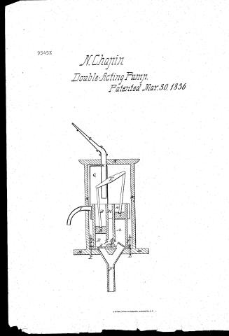
Nathan Chapin's Patent Drawing for a Forcing Pump

National Archives, Restored Patent Drawings (Record Group 241) · Full-size scan at the National Archives · Catalog record
Show the text on the drawing Hide (98 words)
Words on the drawing as machine-read by the National Archives; not checked. Useful mainly for searching.
CLASS (03 PUMPS, / Solid Reciprocating Piston. / N.Chopin / Multiple Cylinder / NA TH CH. / Castened mari 30th 1836 / Forcing Pump / Patented 30 March 1836 / CLASSI. TICATION / 9545-X / DIV ISION. / Walhan bhapir / 9545X / Explanation of the / A.B. Working Barrels / CD. Piston's / I Lever / I Suction pipe / G Connection pipe / H Reservoir / I Syphon / k Discharging Pipe / LL Bolts. / M Base / Wooden Case / o Direction Pipe:- / NY / P.P. Orifices / R Air Vessel / RR Lower Values / S Upper Valve / of / FI / I.I. Iron Collar / It
USPTO scan
The patent as scanned by the USPTO
-
 Page 1
-
 Page 2
-
 Page 3
-
 Page 4
-
 Page 5


U.S. Patent and Trademark Office · Google Patents
Show the transcription Hide (1,236 words)
Machine transcription (LightOnOCR) of the pages as scanned by the USPTO, most of them the handwritten copies made when the records were restored after the 1836 fire. Not checked; it can misread handwriting, so compare it with the scan.
Page 1.
9545X
N. Chapin
Double-Acting Pump.
Patented Mar. 30, 1836

Page 2.
Mar. 30, 1836
Nathan Chapin, of Penns. State of New York.
Letters Patent.
The schedule refers to in these Letters Patent and making part of the same, containing a description in the words of the said Nathan Chapin himself of his improvement in the forcing pump.
To all to whom these presents shall come.
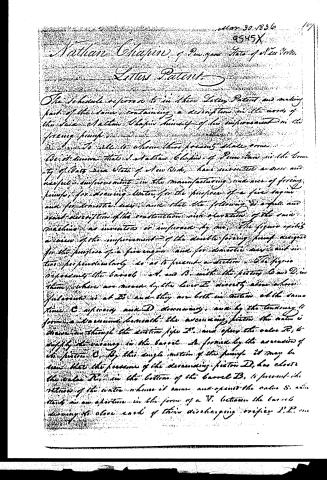
Be it known that I, Nathan Chapin, of Penns. in the County of Bays, State of New York, have invented a new and useful improvement in the manufacturing and use of forcing pumps, for drawing water, for the purpose of a fire engine and for domestic uses, and that the following is a full and exact description of the construction and operation of the said machine, as invented or improved by me. The figure exhibits a view of the improvement of the double forcing pump, designed for the purpose of a fire engine and for domestic uses, and in two perpendiculars so as to present a section. The figure represents the barrel A and B, with the pistons C and D, in them, where are moved by the lever E directly above where fulcrum is at F, and they are both in motion at the same time, C upwards and D downwards, and by the tendency it forms a vacuum beneath the ascending piston, the water is drawn in through the suction pipe H, and opens the valve R, to supply the vacuum in the barrel A, formed by the ascending of the piston C. By this single motion of the pump, it may be seen that the pressure of the descending piston D, has closed the valve R, in the bottom of the barrel B, to prevent the return of the water whence it came, and opens the valve S, which stands in an aperture in the form of a V, between the barrels, allowing to close each of their discharging orifices L, L, one
Page 3.
at a time, it being necessary to close upon me at the instant it rises from the other, to prevent a current between the barrels, and giving the depressed water a safe ejection through the connection pipe Q into the receiver H which surrounds the total of both barrels. It serves to regulate the current of water by the admittance and escape of air through the forcing pipe H, as it is discharged through the siphon I. This irregularity would be produced by discharging the barrels one at a time. Q represents an air vessel which is connected with the receiver H, and is only used when the siphon I is at stopped for the purpose of forcing water through the pipe H, into an upper room, or by the addition of the direction pipe, C, for the fire engine use. This acts upon the water when passing through the pipe H, and keeps it in regular and uniform motion. The Machine is fastened upon its base H, by means of the bolts I, I, passing through an iron collar I, I, which surrounds the bottom of the barrel, which rests upon a flange at the division of the barrel from their base, at A. At B represents the case which encloses the machinery, and is fastened to the base by lacing.
The use and principle of working it is believed is sufficiently explained in the foregoing description, and it may be applied it will be seen for drawing water from a well or cistern, or liquid from any vessel, and by stopping tightly the siphon I may serve to draw water into an upper room, or as a fire engine by means of the direction pipe C. It is cheap, convenient, and simple, and its construction that any person of ordinary understanding may take it apart and repair it, or remove obstructions if required, without applying to a professional mechanic.
The invention and improvements on the above forcing pump, now in use, for which a patent is claimed, consists in the invention of the valve B, which has a double elevation in allowing to stop the orifice P, P, one at a time, thus when the piston D, in the barrel B is descending, it
Page 4.
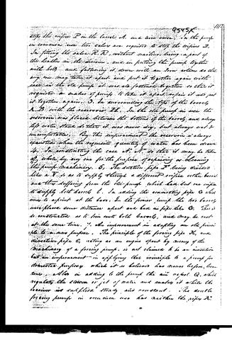
stops the orifice P in the barrel A, and vice versa. In the pump in common use two valves are required to stop the orifice P. In fitting the valve R, R, without making, being a part of the leather in the division, and in putting the pump together with bolts and fastening it down with an iron collar so that any one may take it apart and put it together again with ease in the old pump it was all fastened together so that it required a maker of pumps to take it apart, repair it and put it together again. 3. In surrounding the tops of the barrels A, B with the reservoir H. In the old pump in use the reservoir was placed between the bottoms of the barrels and always left water stand so that it was never dry, but always wet & uncomfortable. By this improvement the reservoir is always separate when the requisite quantity of water has been drawn. 4. In constructing the case C, C, so that it may be taken off wholly by any one for the purpose of repairing or cleaning the pump machinery. 5. The suction pipe F being divided like a V so as to supply through a different orifice each barrel and thus suffering from the old pump which had but one orifice to supply both barrels. In adding the connecting pipe G which comes to a point at the base. In the former pump the two barrels were placed some distance apart and had no pipe like G. This is so constructed as to join into both barrels, and may be cast at the same time. 7. The improvement in adapting an old principle to a new purpose. The principle of the forcing pipe K, and direction pipe G, acting as an engine spent by means of the machinery of a forcing pump, is not claimed to be an invention but an improvement in applying that principle to a pump for domestic purposes which it is believed has never before been done. Also in adding to the pump the air vessel Q, which regulates the stream or jet of water and makes it while the reservoir is supplied steady and constant. The double forcing pump in common use has neither the pipes K.
Page 5.
12.
or O, nor the air vessel G, but is employed to the purpose of drawing water through a siphon like I. The Engine pump may be made on a small scale and from the nature of its construction of the most durable materials and will occupy a very small place in a kitchen.
In testifying that the within is a true specification of my said improvement as within described I have hereunto set my hand the 20th day of March in the year of our Lord One thousand eight hundred and thirty six.
Witness
Henry A. Wimer
John L. Lewis, Just.
Nathan Chapin
[Drawing in Portfolio]
Filed 4/19/36
Published accounts: journal notice
Notice in the monthly list of patents
Journal of the Franklin Institute, new ser., vol. 17 (1836), p. 439 · View the page
252. Forcing pump.-Nathan Chapin, Penn Yan, N. York,
About this record
- Patentee
- DATAMP
- Date
- the Name and Date index of patents, DATAMP, USPTO records
- Invention
- DATAMP
- Listed in
- the Name and Date index of patents, DATAMP, USPTO records, Jim Shaw's X-patent list, the Journal of the Franklin Institute, Burke's List of Patents (1847)
- Burke's 1847 Patent Office list gives the same patent.