

Drawings and documents
National Archives restored drawings: drawing
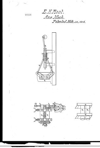
Elisha K. Root's Patent Drawing for an Axe Machine

National Archives, Restored Patent Drawings (Record Group 241) · Full-size scan at the National Archives · Catalog record
Show the text on the drawing Hide (171 words)
Words on the drawing as machine-read by the National Archives; not checked. Useful mainly for searching.
12 / 76. METAL WORKING, / Axes and Hatchets. / IK. IR / IIA / a x E / Scale, 1/2 inch to the foot. / Patented 30th March 1836. / bol 27 page 425 / 9553.X / F. / of / DIVISION. / 9553 X / B. / OFF / A. / L.L. / B. / A. / D. / R E F E R E N c E s / A.A. The roller frames. / B.B. The Rollers. / C.C. the Dies. for plating / D.D. the welding Dies. / P.P. The projections for Mostering . / E.E. the projections to drive eye pin. / 0.0. the novorow dies for edging / T1. The Rack and slide. / N.N. the toggle joints, to open and shut jaws. / M. M. The gams. / B. / F. F. the deavers, or bams, on the ends of rollers. / 6.G. the Proceps. with their joints. / H. / the barriage. / B. / i.i. The Latches. / J. the Sliding rod / K. the Pitman, or main sweep, with its joints / I.L. the brank. / X.X. the projections, or Shoulders en sliving rod. / GB
USPTO scan
The patent as scanned by the USPTO
-
 Page 1
-
 Page 2
-
 Page 3
-
 Page 4
-
 Page 5


U.S. Patent and Trademark Office · Google Patents
Show the transcription Hide (1,505 words)
Machine transcription (LightOnOCR) of the pages as scanned by the USPTO, most of them the handwritten copies made when the records were restored after the 1836 fire. Not checked; it can misread handwriting, so compare it with the scan.
Page 1.
9553X
E. H. Root.
Axe Mach.
Patented Mach. 30-1836.

Page 2.
3/30/1836 9553X
Mar. 30, 1836 425
Elisha K. Axt of Canton, County of Hartford & State of Connecticut.
The schedule referred to in this Letter Patent, and making part of the same, containing a description in the words of the said Elisha K. Axt himself, of his "Improvement in manufacturing Axes"
To all whom it may concern.
Be it known that I Elisha K. Axt of Canton in the County of Hartford and State of Connecticut have invented an improvement in the mode of manufacturing Axes, or forging the axes of which the axes are to be made into its proper form; and of doubling and welding the same by pressure between Rollers & otherwise and that the following is a full & exact description of the same. The use of Rollers & form the iron, or their application to the forming Iron for axes is not claimed, but this improvement consists in placing and fastening on dies of suitable form to Rollers which instead of revolving in a rotary manner as has heretofore been done, are made to revolve partly round & back again, & thus compress & mould into proper form one end of the heated Iron, which requires to be twice compressed in two dies successively while the other end is held by the workman in the tongs, and then by changing ends of the pattern of Iron to compress & form the other end of it between the other dies as before, which dies correspond as right and left handed ends of the same pattern, — and after each compression thus performed, the Rollers by their returning motion render back the pattern of heated Iron to the workman, and while the iron is yet hot it is bent and doubled in another part of the machine, once compressed into a suitable form for welding, then the heat being suitably raised or increased the pattern is welded by another compression between another pair of dies, which at the same time give the proper form to the bit of the axe to receive the steel. — All the subsequent operations of welding in the steel and finishing the axes are done in the usual way by the hammer. — For the first operation above named, a pair of strong iron Rollers are placed in a strong iron frame as a usual in rolling mills, and the tops of the upper roller made movable by strong setting screws to set the rollers at suitable distance from each other, but in this arrangement the surface of the rollers should be much farther apart than those
Page 3.
of common rolling mills, so as to admit a pair of dies to be fastened by screws or otherwise to the rollers—the plate of each of these dies should be from one and a half to three inches thick, and these dies I consider to be best made of cast iron, with suitable indentations or depressions and projections to suit the desired form of the work, and so placed on the rollers as to meet and agree with each other.
The journals or guidions of the rollers pass through or by the frame which sustains them, at both ends so as to project about eight or twelve inches on each end outside of the frame. Motion is given to the rollers by strong levers or cams attached to their projecting ends on one side of the frame, and these levers are connected by screws to a crank on the shaft of a fly wheel, by which means an alternate motion forward and backward is given to the rollers, and the screws are so connected with the crank as to be easily disconnected at pleasure to stop the motion of the rollers and other works, & to set them in motion again with equal facility.
On the lower roller at its projecting end, back of the lever, & between the lever & the frame is placed the segment of a pinion which gears into a rack which is thereby made to slide back and forth alternately as the rollers move back and forth. The rack with its slide is connected to a pair of strong iron jaws which are by that means opened and shut, moving a short distance, but with great force. This rack & slide also moves a large punch, or tongue of iron into a recess between two small rollers, placed about three or four inches apart, and the punch enters & reaches about three or four inches between them, & the heated pattern after being plated and formed between the dies on the large rollers, is placed in front of the recess between these small rollers, & the thickest part of the pattern is thrust forward by the punch which thus bends or doubles the pattern, which is then placed between the jaws before described, which are more open at their outer ends & approach nearer & nearer together to their fulcrum, and by some successive compressions between these jaws beginning at their outer ends, the pattern is bent more and more closely until the eye and head of the axe is formed suitably for working. On the projecting ends of the large rollers, and on the outside of the frame opposite to the levers which move the rollers are placed a pair of projections suitable to support and form the ends of the axe, and also a pair of narrow dies suitable to form the lateral edges or bevels.
Page 4.
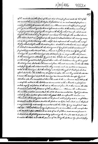
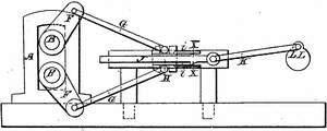
of it, and also another pair of broad dies to compress and weld the "bit" of the axe and at the same time to shape it flatwise in an oval and prepare for ready for slitting to receive the steel. There are several different ways of giving an alternating backward and forward motion to the rollers, and also of engaging and disengaging the scrapers with the fly wheel crank which would suggest themselves to any competent mechanic but I prefer the method herein after described and exemplified in the model, and illustrated in the drawing annexed as being better than any other. Let L, L, represent the crank on the end of the fly wheel shaft, with its wrist or pin, to which is attached the main scraper K, which is connected with the sliding rod J, by a joint which has no projecting or shoulder at XX. This rod is fitted to slide easily through the carriage H, and this carriage also slides freely on ways within the frame, and this carriage is attached by joints to latches L, which fit the shoulders on the sliding rod to catch against them when the latches are brought in against the sliding rod, but when thrown out from the rod one or two inches the latches will pass by the shoulders, and while they remain out no motion is communicated to the carriage, but the sliding rod slips through it back and forth to no effect, but when the latches are dropped in upon the rod they catch the shoulders and move the carriage, and to the carriage are connected two scrapers by joints G, G, these also are connected at their other ends to the L - levers or cams K, K, on the ends of the rollers, and the latches are so connected with a trundle or foot-piece as to be easily let fall on to the rod or thrown out from it, and thus cause the rollers to move or rest at the pleasure of the workman. When on the rollers move, the crank and slide move also, and the slide is so connected to a "toggle" joint, and which by their motion open and shut the jaws M, M, in a forcible manner. The crank and slide also gives motion to the punch, while forcing into a recess below two small rollers bends or doubles the pattern as before described, and this punch is very naturally and easily connected with the slide by any competent mechanism. That I claim as my improvement and invention, is the use of rollers with metallic jaws attached to one side of each of them, and moved forward and backward in the plating and welding and forming the iron for axes to prepare it to receive the steel, and also the manner of doubling the patterns by a punch forcing
Page 5.
3/30/1836 9553x
425.
between two small rollers, and afterwards completing the doubling by confining between two jaws both of which move alike in approaching each other, and also the method herein described for connecting and disconnecting the crank and rollers.
Witnesses
Eph. Saml. H. Collins
H. H. Reuben Shinn
Elisha K. Root.
(1485 words)
Patented March 30, 1836
Drawing
Published accounts: journal notice
Notice in the monthly list of patents
Journal of the Franklin Institute, new ser., vol. 17 (1836), p. 439 · View the page
251. Axes, manufacturing.-Elisha R. Root, Canton, Conn.
DATAMP: illustration
Illustrations from DATAMP

DATAMP (Directory of American Tool and Machinery Patents), via the Internet Archive · Archived DATAMP page
About this record
- Patentee
- DATAMP
- Date
- the Name and Date index of patents, DATAMP, USPTO records
- Invention
- DATAMP
- Listed in
- the Name and Date index of patents, DATAMP, USPTO records, Jim Shaw's X-patent list, the Journal of the Franklin Institute, Burke's List of Patents (1847)
- Burke's 1847 Patent Office list gives the same patent.