

Drawings and documents
National Archives restored drawings: drawing
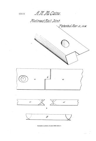
A.M. McCaines Patent Drawing for an Improved Mode of Joining Rail Plates and Bars Used Upon Rail Roads

National Archives, Restored Patent Drawings (Record Group 241) · Full-size scan at the National Archives · Catalog record
Show the text on the drawing Hide (29 words)
Words on the drawing as machine-read by the National Archives; not checked. Useful mainly for searching.
104 104. A VS IS. / RAIM WOINTS, / Li20] Rail Joints. / 104, RAILWAYS / RAIL JOINTS, / Soari / of
USPTO scan
The patent as scanned by the USPTO
-
 Page 1
-
 Page 2
-
 Page 3
-
 Page 4


U.S. Patent and Trademark Office · Google Patents
Show the transcription Hide (850 words)
Machine transcription (LightOnOCR) of the pages as scanned by the USPTO, most of them the handwritten copies made when the records were restored after the 1836 fire. Not checked; it can misread handwriting, so compare it with the scan.
Page 1.
9567X
A.M. McCaine.
Railroad Rail Joint.
Patented Mar. 31, 1886.

THE GRAPHIC CO. PHOTO-LITH. 39 & 41 PARK PLACE, N.Y.
Page 2.
Mar 31, 1834 13
A. Messick & Co. of Montgomery, Alabama
Letters Patent 9567X
March 31, 1834
The Schedule referred to in these Letters Patent, and
making part of the same, containing a description in the
words of the said A. Messick & Co. himself of his improve-
ment in joining rail plates or bars, used upon rail roads.
Be it known that I, A. Messick & Co. of the Town of Montgomery
in the County of Montgomery and State of Alabama, have
invented a new and useful improvement in the mode of
joining the rail plates, or bars used upon rail roads, which
is described as follows, reference being had to the annexed
drawings of the same, making part of this specification.
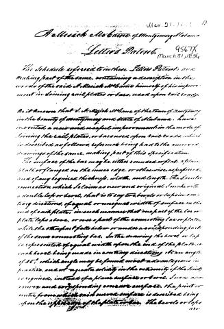
The surface of the bars may be either rounded or flat, a plain
plate or flanged on the inner edge, or otherwise, as preferred,
and of any required thickness, width, and length. The former
connection which I claim as new and original, I make with
a double lap or bevel, that is to say two bevels or laps in con-
tary directions, of equal or unequal width of surface on the
end of each plate, in such manner that one part of the bar or
plate laps above, or over a part of the connecting bar or plate,
while the other part falls below or under a corresponding part
of the same connecting bar. In the drawing the bevel or lap
is represented of equal width upon the end of the plate, or
each bevel being made in contrary directions at an angle
of 45°, which angle may be found most advantageous in
practice, and at a greater solidity in the extremity of the bar,
is required, instead of a plane surface or bevel. Such are
the inner and corresponding concave surface, the point or
centre from which said inner surface is described being
upon the upper edge of the plate or bar. The bevels or laps
(10)
Page 3.
14. 9507X
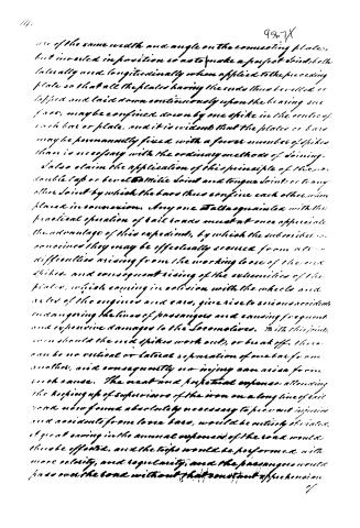
use of the same width and angle on the connecting plates, but inverted in position so as to make a perfect double bell lateral and longitudinally when applied to the preceding plate so that all the plates having the ends thus beveled or lapped, and laid down continuously upon the bearing surface, maybe confined down by one spike in the center of each bar or plate, and it is evident that the plates or bars may be permanently fixed with a fewer number of spikes than is necessary with the ordinary methods of joining.
I also claim the application of this principle of the double lap or bevel to the joint and tongue joint, or to any other joint by which the bars thus confine each other when placed in connection. Anyone familiar with the practical operation of rail roads must at once appreciate the advantage of this expedient, by which the subscribers are convinced they may be effectually secured from all difficulties arising from the working loose of the end spikes, and consequent rising of the extremities of the plates, which coming in collision with the wheels and axles of the engines and cars, give rise to serious accidents endangering the lives of passengers and causing frequent and expensive damages to the locomotives. With this joint, even should the end spikes work out, or break off, there can be no vertical or lateral separation of one bar from another, and consequently no injury can arise from such cause. The neat and perpetual expense attending the keeping up of superiors of the iron on a long line of rail road now found absolutely necessary to prevent injuries and accidents from loose bars, would be entirely obviated. A great saving in the annual expenses of the road would thus be effected, and the trips would be performed with more velocity, and regularity, and the passengers would pass over the road without that constant apprehension of
Page 4.
9567X
images, which the prospect of loose bars, and broken sides and raised plates is so well calculated to awaken.
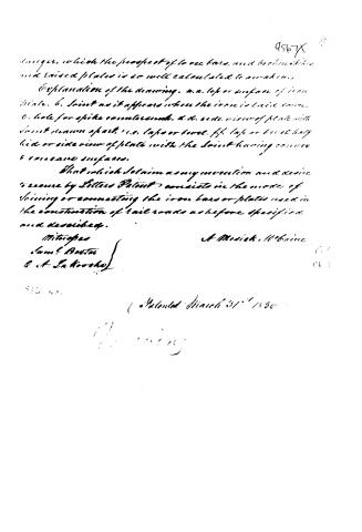
Explanation of the drawing. a.a. top or surface of iron plate. b. Joint as it appears when the iron is laid down. c. hole for spike counter-sunk. d.d. side view of plate with joint shown apart. e.e. lap or bond. f.f. lap or bond half hid or side view of plate with the joint having convex & concave surfaces.
That which I claim as my invention and desire to secure by Letters Patent, consists in the mode of joining or connecting the iron bars or plates used in the construction of rail roads as before specified and described.
Witnesses
Sam'l Baxter
O. A. La Troche
A. Mosick, Urbaine
Filed March 31st 1836
O. Mosick
About this record
- Patentee
- DATAMP
- Date
- the Name and Date index of patents, DATAMP, USPTO records
- Invention
- DATAMP
- Listed in
- the Name and Date index of patents, DATAMP, USPTO records, Jim Shaw's X-patent list, Burke's List of Patents (1847)
- Burke's 1847 Patent Office list gives the same patent.